1
unitech
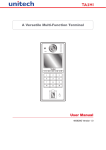
MR650 TASHI Terminal
unitech
F1
F2
F3
F4
ESC
E
User’s Manual
400513G Rev. H
Preface
About the MR650 User’s Manual
This manual explains how to install, operate and maintain the MR650 TASHI Terminal.
No part of this publication may be reproduced or used in any form, or by any electrical or
mechanical means, without permission in writing from the manufacturer, which includes but is
not limited to photocopying, recording, or information storage and retrieval systems. The
material in this manual is subject to change without notice.
© Copyright 2008 Unitech Electronics Co., Ltd. All rights reserved.
Unitech America Web site: http:\\www.ute.com
Microsoft, Windows and ActiveSync are either registered trademarks or
trademarks of Microsoft Corporation. Other product names mentioned
in this manual may be trademarks or registered trademarks of their
respective companies and are hereby acknowledged.
Regulatory Compliance Statements
FCC Statement
This is a FCC Part 15 Class A product. In a domestic environment this product may cause
radio interference, in which case the user may be required to take adequate measures.
Canadian Compliance Statement
This Class A Digital apparatus meets all requirements of the Canadian Interference-Causing
Equipment Regulations.
Cet appareil numérique de la classe A respecte les exigences du Règlement sur le matériel
broilleur du Canada.
European Conformity Statement
Declaration of Conformity with Regard to the R&TTE 1999/5/EC and EMC 89/336/ EEC directives.
RoHS Statement
This device conforms to RoHS (Restriction of Hazardous Substances) European Union regulations that set maximum concentration limits on hazardous materials used in electrical and electronic
equipment.
i
Notices
The MR650 is equipped with a Lithium-Ion battery pack. However, the MR650 may not start
without an external power source due to battery discharge after extended storage periods. To
charge the battery to full capacity, connect the MR650 with the AC Adapter and charge the
MR650 for at leaset 22 hours.
The battery supplies operational power to the MR650 for approximately two hours (configuration and backlight use dependant) or provides backup data for up to three days without an
external power source.
Battery Charge Notice
It is important to consider the environmental temperature whenever the Lithium-Ion battery
pack is charged. Charging is most efficient at room temperature or in a slightly cooler environment. It is essential that batteries charge within the temperature range of 23°F to 122°F.
Charging batteries outside of this specified temperature range could damage the batteries
and shorten their charging life cycle.
Battery Storage and Safety Notice
Charged Lithium-Ion batteries may be left unused for several months, but their capacity may
be depleted due to buildup of internal resistance. In this case they will require recharging. Lithium-Ion batteries may store at temperatures between -4°F to 140°F. But the batteries may
deplete more rapidly at the warmer end of this range. It is recommended to store batteries at
room temperature.
MR650 Warranty
Unitech limited Warranty covers the following items:
• MR650 TASHI Terminal - 1-year limited warranty.
• MR650 Cables - 1-year limited warranty.
• MR650 Backup Battery - 3-month warranty.
ii
Table of Contents
Preface
About The MR650 User’s Manual .........................................................i
Regulatory Compliance Statements ................................................................i
FCC Statement ........................................................................................................................ i
Canadian Compliance Statement ............................................................................................ i
European Conformity Statement ............................................................................................. i
RoHS Statement ...................................................................................................................... i
Notices ...............................................................................................................ii
Battery Charge Notice .............................................................................................................ii
Battery Storage and Safety Notice ..........................................................................................ii
MR650 Warranty ................................................................................................ii
Chapter 1
Getting Started .................................................................................... 1
Introducing the MR650 .....................................................................................1
Features ................................................................................................................................. 1
Package Contents .............................................................................................2
MR650 Overview ................................................................................................3
Front Panel ............................................................................................................................. 3
Back Panel ............................................................................................................................. 3
Setting up the MR650 .......................................................................................4
Open Backplate ...................................................................................................................... 4
Connect Power ....................................................................................................................... 5
Starting the MR650 ...........................................................................................6
Powering On ........................................................................................................................... 6
Using the Stylus ...................................................................................................................... 6
Calibrate Screen ..................................................................................................................... 6
Setting Date and Time ............................................................................................................ 7
Chapter 2
Using the Hardware ............................................................................. 8
Using the Keypad .............................................................................................8
Using Windows CE Keyboard ................................................................................................. 9
Entering Characters ........................................................................................................... 9
Numeric Character ............................................................................................................ 9
Moving the Keyboard ......................................................................................................... 9
Closing the Keyboard ........................................................................................................ 9
Using the Proximity MSR or Bar Code Reader ............................................10
Testing Reader Data ............................................................................................................. 10
Using the MiFare Reader ................................................................................11
Testing the MiFare Card Verification .................................................................................... 11
Using the Fingerprint Reader ........................................................................13
Testing Finger Print Verification ............................................................................................ 13
Enrolling a Fingerprint Stamp .......................................................................................... 14
Verifying the Fingerprint Stamp ....................................................................................... 14
iii
Using the Camera ...........................................................................................15
Testing the Imager ................................................................................................................ 15
Chapter 3
Data Communication ......................................................................... 16
Establishing an MR650/PC Connection ........................................................16
Serial Cable .......................................................................................................................... 16
Ethernet Cable ...................................................................................................................... 16
Wireless Communication ...................................................................................................... 17
RF Communication ............................................................................................................... 17
Using Microsoft ActiveSync ..........................................................................18
Additional Microsoft ActiveSyce Capabilities ................................................................... 18
Microsoft ActiveSync Requirements ................................................................................ 18
Installing Microsoft ActiveSync ............................................................................................. 18
Connecting the MR650 to a Computer ................................................................................. 19
Setting up the Wireless Local Area Network Card ................................................................ 21
Obtaining an IP Address via DHCP Server ..................................................................... 21
Specifying an IP Address ................................................................................................ 22
Wi-Fi Connection ............................................................................................................. 23
Chapter 4
Bar Code Scanner Programs ............................................................ 25
Scanner Settings ............................................................................................25
Scan2Key .........................................................................................................25
Registry Backup/Restore ...............................................................................26
Audio Demo Program .....................................................................................27
Chapter 5
Power System ................................................................................... 28
Charging the Backup Battery for the First Time ..........................................28
Checking the Battery Status ................................................................................................. 28
Extending Battery Life ....................................................................................29
Changing the Automatic Power Settings .............................................................................. 29
Reducing CPU Speed ........................................................................................................... 29
Adjusting the Backlight ......................................................................................................... 30
Performing a Hardware Reset .......................................................................31
Performing a Warm Start ...................................................................................................... 31
Performing a Cold Start ........................................................................................................ 31
Appendix A
System Specification ......................................................................... 32
Appendix B
Terminal Block ................................................................................... 33
Overview of the MR650 Terminal Block ........................................................33
MR650 Terminal Block Pin Assignment .............................................................................. 34
Appendix C
Worldwide Support ............................................................................ 36
iv
Chapter 1
Getting Started
Introducing the MR650
Thanks for purchasing the MR650 TASHI (Time & Attendance, Access Control, Security, Home Automation and Intercom) Terminal. The MR650 is designed to meet the requirements of Time & Attendance, Loyalty Programs and Work-In-Progress applications. It communicates with central host and
T&A systems through standard Ethernet or WLAN networks. The built-in CMOS digital camera, microphone and audio speaker provides complete area security in a single compact device. The MR650 features a variety of built-in readers including proximity and fingerprint identification. It also includes
programming tools and support software for developing custom security.
Features
System
•
•
•
•
Microsoft Windows CE 5.0 Professional
Plus.
520Mhz Intel PXA270 Processor.
128 MB SDRAM.
64 MB Flash ROM.
Display
•
5.6” QVGA (240 x 320 pixel) LCD Touchscreen.
Multimedia
•
•
•
1.3 Megapixel CMOS Color Camera.
Audio Output via 0.8 Watt Speaker.
Built-in Microphone.
Expansion Slot
•
CF Type II Card Slot for Wireless
802.11 b/g.
•
SD Memory Slot.
Magnetic Stripe Reader
•
3-track MSR Reader.
Fingerprint Reader
•
•
•
•
Sensor: Authentec AFS8500.
Verification Time: 2 Seconds (Average).
Equal Error Rate: 0.1% at Max Security.
Number of Templates: 4,000.
Proximity Reader
•
•
•
EM, 125kHz.
HID, 125kHz.
MiFare, 13.56Mhz.
Wireless Connectivity
•
802.11b/g (optional).
Communication
•
•
•
•
•
•
RS232.
USB Host.
Output Relays (3).
TTL Digital Inputs (4).
Ethernet Connection.
Power-over-Ethernet (optional.)
Battery Life
•
•
•
Operation Time: 2 hours.
Charging Time: 22 hours.
Embedded Backup Battery.
User Interface
•
•
Six Hard Keys.
Touch-screen with Stylus.
Software Programming Tools
•
•
Embedded Visual Basic Terminal Program for T&A.
Embedded Visual C++ Terminal Program
for T&A.
1
Package Contents:
Make sure the following items are in the MR650 box:
unitech
F1
F2
F3
F4
unitech
ESC
E
F1
MR650 Proximity + Fingerprint
Model
F2
F3
F4
unitech
ESC
E
F1
MR650 Proximity Model
F2
F3
F4
ESC
E
MR650 with 3-Track MSR
or Bar Code Reader Model
AC Adapter
Stylus
RS232 Cable
Manual CD-ROM and Unitech MR650 Quick
Reference Guide
Please contact a Unitech representative if anything appears missing or damaged.
NOTE:
2
A plastic film covers the screen on a new MR650. Remove the plastic film by peeling
back from one corner to another. Without the plastic film the MR650 is more susceptible to scratching. But, the MR650’s display is more legible.
Copyright 2008 unitech Electronics Co., Ltd. All rights reserved. unitech is a registered trademark of unitech Electronics Co., Ltd.
Chapter 1 Getting Started
MR650 Overview
Front Panel
unitech
3-Track
MSR
Reader
F1
F4
F3
ESC
E
MR650 MSR Model
Speaker
Microphone
F2
unitech
1.3 Megapixel
CMOS Camera
unitech
Proximity
Reader
Proximity
Reader
5.6” Color
Touch-screen
Fingerprint
F1
6-key Keypad
F1
F2
F3
F4
ESC
F2
F3
F4
ESC
E
E
MR650 Proximity + Fingerprint Model
MR650 Proximity Model
Back Panel
Backplate Hooks
Mounting
Holes
Mounting
Holes
Terminal Block
Security Lock
3
Setting up the MR650
This section explains how to charge the battery and how to start the MR650 for the first time.
Open Backplate
1.
Insert the MR650 key into the security lock and
turn counterclockwise.
2.
Lift the backplate up to a 45-degree angle (1)
and pull the backplate out from under the backplate hooks (2).
2
Backplate Hooks
1
3.
Flip the backplate over to the left side.
Be Careful
Not to
Stretch this
Cable
4
Copyright 2008 unitech Electronics Co., Ltd. All rights reserved. unitech is a registered trademark of unitech Electronics Co., Ltd.
Chapter 1 Getting Started
Connect Power
Follow these instructions to connect power to the MR650:
NOTE:
1.
Charge the MR650 for at least 22 hours prior to initial use. The battery starts charging
as soon as the MR650 connects to a power source.
Insert the AC Adapter through the backplate and into the Terminal Block Connector.
Terminal Block
Connector
2
1
2.
3.
4.
Plug the other end of the AC Adapter into a power source.
To charge the MR650 battery, use a stylus to move the Battery Switch to the On position.
Close and lock the backplate.
Off
On
5
Starting the MR650
Powering On
The MR650 automatically starts when the AC Adapter plugs into a power source. The MR650 welcome
screen appears followed by the Windows CE screen.
Using the Stylus
CAUTION! Never use anything other than the MR650 stylus on the MR650’s
screen. Using an object other than the stylus could cause permanent
damage.
1.
2.
3.
4.
Hold the stylus like a pencil.
Lightly tap the tip of the stylus to make a menu choice.
Double-tap to open programs.
Use the stylus to print letters or numbers into a field or on a form.
Calibrate Screen
The calibration screen automatically appears when the MR650 powers on for the first time, or after the
system is reset.
Use the stylus to tap a sequence
of target marks on the MR650’s
screen. Firmly hold the stylus on
top of the target mark for a
moment, and then remove. Continue to tap the target mark as it
stops along the corners of the
screen.
After the calibration setting is
complete, press the E key to
save the setting, or press ESC to
cancel the setting.
The Date/Time Properties window automatically appears after the calibration setting is complete.
6
Copyright 2008 unitech Electronics Co., Ltd. All rights reserved. unitech is a registered trademark of unitech Electronics Co., Ltd.
Set Date and Time
In the Date/Time Properties window, use the
stylus to select the current date and time, time
zone, and daylight saving time option.
•
•
•
•
•
Tap the left or right arrows to scroll
through the year and month, or tap
the year and month to select the setting.
Tap on the Hr/Min/Sec/AM/PM to
input the Hr/Min/Sec and set the time.
Tap the arrow and set the correct time
zone from the drop down menu.
Check the box to enable Windows to
automatically adjust for daylight
saving time.
Tap OK to save the settings and exit
the Date/Time Properties dialog or tap
X to exit without saving.
NOTE:
To change the time and date
at any time tap
→ Settings → Control Panel →
Double-tap Date/Time.
Set Date
Set Time
Set Time
Zone
Set
Daylight
Saving
Time
7
Chapter 2
Using the Hardware
Using the Keypad
The MR650 features six hard keys.
The following table describes each key.
Key
Main Function
Clock in:
[F1]: Function Key.
Break out:
[F2]: Function Key.
Break in:
[F3]: Function Key.
Clock out:
[F4]: Function Key.
[ESC] Performs the same function as tapping
on the touch-screen.
[ENTER] Moves the cursor to the next line or executes a command.
8
Copyright 2008 unitech Electronics Co., Ltd. All rights reserved. unitech is a registered trademark of unitech Electronics Co., Ltd.
Chapter 2 Using the Hardware
Using the Windows CE Keyboard
The Windows CE Software provides a touch-screen keyboard for alphanumeric input. The
Windows based keyboard replicates the layout of a standard PC keyboard.
Open the Windows CE keyboard by tapping keyboard on the task bar and tap Keyboard.
Keyboard Icon
Entering Characters
To input a character, tap the onscreen button corresponding to the desired symbol.
Special Character Support:
Tap áü to switch from the Standard English
keyboard to the Special Characters keyboard.
Numeric Keypad
To access the Numeric keypad, select the Keyboard icon on the taskbar and tap Numeric Keypad.
Title Bar
Moving the Keyboard
Tap the title bar to drag and place the keyboard across the screen.
Closing the Keyboard
Tap the keyboard icon and tap Hide Input
Panel to close the Windows CE keyboard.
Tap Here to Enter Special
Characters
9
Using the Proximity, MSR or Bar Code Reader
The MR650 features an integrated
proximity reader (EM125kHz, HID
125kHz and 13.56Mhz MiFare), MSR,
and bar code reader which can read
proximity cards, magnetic stripe cards
and bar code labels.
NOTE:
Place or
Swipe Card
Here
unitech
unitech
The reading software
must be enabled in
order to operate the
scanner.
This is achieved
through a user loaded
application or a preloaded utility like a scanner setting.
F1
F2
F3
F4
ESC
E
F1
F2
F3
F4
unitech
ESC
E
F1
F2
F3
F4
ESC
E
Testing Reader Data
The MR650 has a built-in Scanner Control Panel that can test the MR650’s bar code scanner.
1.
2.
3.
10
To open the Scanner Control Panel, tap
→ Settings → Control Panel → Double-tap Scanner.
From here users can configure bar code scanner parameters such as enabling or disabling bar code symbologies, set
data transmission options, configure magnetic and proximity
reading options, and set power management options.
To test the bar code scanner, tap the Test tab and slide a
card through the scanner slot. The screen will display the
scan results.
Copyright 2008 unitech Electronics Co., Ltd. All rights reserved. unitech is a registered trademark of unitech Electronics Co., Ltd.
Chapter 2 Using the Hardware
Using the MiFare Reader
The MR650 has an optional integrated MiFare
reader that verifies card readouts in just a few
seconds.
unitech
Bring a MiFare Card
Near Here for Reading
F1
F2
F3
F4
ESC
E
Testing the MiFare Card Verification
The MR650 has a built-in MifareDemo program that enables the user to make MiFare card verifications.
1.
Double-tap the My Device icon on the Windows CE
desktop.
2.
Double-tap the Windows folder.
11
12
3.
Double-tap MifareDemo to open the program.
4.
Tap Connect to activate the program.
5.
Tap Start Read and bring the MiFare card close to the sensor. The code will be read and displayed on the field below.
6.
Tap Stop Read to end the MiFare reading.
Copyright 2008 unitech Electronics Co., Ltd. All rights reserved. unitech is a registered trademark of unitech Electronics Co., Ltd.
Chapter 2 Using the Hardware
Using the Fingerprint Reader
The MR650 has an optional integrated Fingerprint reader that has a verification of less than
two seconds. The Fingerprint Reader is available with 4,000 fingerprint stamp templates.
unitech
Place Finger Here
for Reading
F1
F2
F3
F4
ESC
E
Testing the Fingerprint Verification
The MR650 has a built-in BioID Manager program that enables the user to test the fingerprint verification function. Any one of 10 fingers can scan into the MR650.
1.
Double-tap the My Device icon on the Windows CE
desktop.
2.
Double-tap the Windows folder.
13
3.
Double-tap BioIDMgr to open the program.
4.
Tap Open to activate the BioIDMgr program.
Enrolling a Fingerprint Stamp
1.
2.
3.
4.
Tap Enroll.
Enter an ID number for the fingerprint and then tap
OK.
The following message appears: Put finger.
Place the finger on the sensor three times.
The ID number stores into the program record.
Verifying the Fingerprint Stamp
1.
2.
3.
4.
5.
14
Tap Verify.
Choose the ID number from the ID list.
Tap Yes.
The following message appears: Put finger.
Place the finger on the sensor to verify if the fingerprint is a match.
Copyright 2008 unitech Electronics Co., Ltd. All rights reserved. unitech is a registered trademark of unitech Electronics Co., Ltd.
Using the Camera
The MR650 has a built-in 1.3 Megapixel camera, which provides the following extra functionality:
•
•
•
•
Enables users to capture still pictures when a card is being read.
Checks attendant time with a photo.
Continuously records video.
Functions as an audio/video intercom.
In addition, facial recognition is possible with third party software.
The MR650 has a demo program that enables users to capture a still picture with a card number and
time stamp, when an Electro Magnetic (EM) proximity card is read.
Testing the Imager
1.
Double-tap the My Device icon on the Windows CE
desktop.
2.
Double-tap the Windows folder.
3.
Double-tap CameraDemo to open the program.
4.
Tap Preview → Start.
A continuous image displays enabling users to capture and playback video.
15
Chapter 3
Data Communication
The MR650 enables users to link to a host computer via RS232, Ethernet or an Radio Frequency (RF)
connection for data communication.
Establishing an MR650/PC Connection
Use the following connection methods to link an MR650 with a personal computer:
Serial Cable
1.
2.
Plug the MR650’s RS232 communication cable into the PC’s 9-pin COM port.
Insert the other end of the cable into the MR650’s RS232 interface port.
Ethernet
RS232
Ethernet Cable
1.
2.
Plug an Ethernet cable into the PC’s RJ45 Ethernet port.
Insert the other end of the cable into the MR650’s Ethernet Port.
NOTE: In order for the optional Power-over-Ethernet (POE) module to support power over
the RJ45 Ethernet cable, the client side must have a POE hub.
16
Copyright 2008 unitech Electronics Co., Ltd. All rights reserved. unitech is a registered trademark of unitech Electronics Co., Ltd.
Chapter 3 Data Communication
Wireless Communication
The MR650 supports an optional CF card for 802.11b/g
wireless communication. To install the RF card, remove
the backplate and insert the RF card into the slot.
RF Card
RF Communication
Users can operate the MR650 to link to the internet with Windows CE support of the Transmission Control Protocol / Internet Protocol (TCP/IP).
1.
Tap
→ Settings → Network and Dial-Up Connections.
2.
Double-tap PRISM1 to set up the IP to connect to the
Internet.
NOTE: Contact a system administrator for the IP
settings for this dialog window.
17
Using Microsoft ActiveSync
Users can synchronize and transfer information between a desktop computer and the MR650 through
Microsoft ActiveSync.
Additional Microsoft ActiveSync Capabilities
•
•
•
•
Backup and restore MR650 data.
Copy (rather than synchronize) files between the MR650 and a desktop computer.
Control the synchronization occurrence by selecting a synchronization mode. For example,
synchronize continuously while connecting to a desktop computer or only when a synchronization command is selected.
Select which information types are synchronized and control how much data is synchronized.
For example, synchronize past appointments during the last six weeks.
Microsoft ActiveSync Requirements
To synchronize, Mircosoft ActiveSync version 4.2 or higher must be installed on both the desktop computer and the MR650 terminal. The MR650 terminal ships with Microsoft ActiveSync already installed.
Download and install the most current version of ActiveSync from www.microsoft.com.
Installing Microsoft ActiveSync
Microsoft ActiveSync must be installed on the computer in order to exchange information between the
computer and the MR650. Microsoft ActiveSync is already installed on the MR650.
NOTE:
If a previous version of Microsoft ActiveSync is installed on the computer, uninstall it
first, before installing the latest version of Microsoft ActiveSync. The MR650 TASHI
Terminal requires ActiveSync version 4.2 or higher.
Following these steps to install Microsoft ActiveSync on a computer:
1.
2.
3.
4.
18
Close any open programs, including those that run during startup, and disable any antivirus
software.
Download the ActiveSync software from the Microsoft ActiveSync Download page at:
http://www.microsoft.com/downloads/details.aspx?FamilyID=7269173a-28bf-4cac-a68258d3233efb4c&DisplayLang=en
Browse to the location of the downloaded file, and double-click it. The installation wizard begins.
Follow the onscreen instructions to install Microsoft ActiveSync.
Copyright 2008 unitech Electronics Co., Ltd. All rights reserved. unitech is a registered trademark of unitech Electronics Co., Ltd.
Chapter 3 Data Communication
Connecting the MR650 to a Computer
1.
2.
After Microsoft ActiveSync is installed, connect the MR650 to a PC.
Start the MR650.
3.
Microsoft ActiveSync starts automatically and configures the communication
port to work with the MR650. The New
Partnership setup wizard automatically
starts.
NOTE:
If Mircosoft ActiveSync does
not start automatically, click
→ Programs → Microsoft
ActiveSync.
If a message appears indicating that it is unable to detect a
connection, click Cancel and
manually configure the communication settings. Manually
configure the communications settings on the PC by clicking MAS → File → Connection Setting → Connect Device.
4.
5.
Follow the onscreen instructions.
When the configuration process is
complete, the Microsoft ActiveSync
window appears.
6.
Synchronization will initiate, and it will synchronize periodically or upon connection.
NOTE:
7.
A PC can partner with multiple MR650’s. But, an MR650 can only partner with up to
two computers.
On the MR650, tap
→ Settings → Control Panel → double-tap PC Connection.
19
8.
9.
Check Enable direct connections to the desktop computer.
Tap Change Connection.
10. Select the preferred connection from the drop down
menu. The higher connection number equates to a
faster connection speed.
11. Tap
→ Programs → Communication → double-tap PC Link.
20
Copyright 2008 unitech Electronics Co., Ltd. All rights reserved. unitech is a registered trademark of unitech Electronics Co., Ltd.
Chapter 3 Data Communication
Setting up the Wireless Local Area Network Card
The MR650 automatically detects RF cards during initial installation. One of the following two options
sets up the IP address:
•
•
Obtaining an IP Address via Dynamic Host Configuration Protocol (DHCP) Server.
Specifying an IP Address.
Obtaining an IP Address via DHCP Server
To obtain an IP address via DHCP server, make sure a DHCP server is available in the LAN environment.
1.
Tap
→ Settings → Control Panel double-tap
Network and Dial-up Connections.
2.
3.
Tap PRISM1.
Tap the IP Address tab.
4.
Select Obtain an IP address via DHCP. Tap OK.
21
Specifying an IP Address
To specify an IP address when no DCHP server is available, assign an IP address to the MR650 as follows:
1.
2.
3.
Tap
→ Settings → Control Panel double-tap
Network and Dial-up Connections.
Tap PRISM1.
Tap Specify an IP Address.
4.
Input the proper IP address, Subnet Mask and
Default Gateway.
5.
Tap the Name Servers tab, and then input the proper Primary DNS, Secondary DNS, Primary
WINS and Secondary WINS.
Consulting the MIS department is recommended for avoiding any conflict with the LAN network.
22
Copyright 2008 unitech Electronics Co., Ltd. All rights reserved. unitech is a registered trademark of unitech Electronics Co., Ltd.
Chapter 3 Data Communication
Wi-Fi Connection
The MR650 comes with a built-in RF facility. This chapter explains how to setup the RF setting. After
installing the Wi-Fi card, reboot the MR650 and the Summit Client Utility icon appears on the Windows CE desktop.
1. Double-tap the Summit Client Utility.
2. Select the Main tab in the Active profile drop down
menu, select ThirdPartyConfig.
3. A Power Cycle is required to make settings
active. Tap OK in the SCU box.
23
4. Tap OK on the Summit Client Utility tab.
5. Select Warm Boot in the BootMode Menu.
6. The RF setting Window appears once the RF card is
deteced.
7. Select Add New (Or double-tap a preferred
network) to add a new Service Set Identifier (SSID).
8. Enter the SSID. Uncheck The key is
provided automatically. Enter the network key.
9. Tap OK. Start to search for the RF signal once it connects.
24
Chapter 4 Bar Code Scanner Programs
Chapter 4
Bar Code Scanner Programs
Scanner Settings
In order to change the default bar code symbology for different applications, the Scanner Control Panel allows the
ability to change the default. Place the delimiter behind
the scanned data and save the settings.
Tap
→ Settings → Control Panel → double-tap
Scanner to display the Scanner Control Panel.
Scan2Key
The Scan2Key application routes input from a scanner port
to a keypad buffer. Making all input from the scanner emulate input from the keypad. Using Scan2Key, scanned data
can be directly input into a scanner port aware application
such as MS Pocket Word.
Tap
→ Settings → Control Panel → Scanner → To
Kpd to access Scan2Key settings.
NOTE:
Please refer to the Scan2Key Utility Manual
to refer to the Scan2key Utility Manual.
25
Registry Backup/Restore
Registry Backup enables users to save current registry settings. If the system malfunctions or settings
are lost, the user can go to Registry Restore to retrieve settings.
To use Registry Backup:
Tap
2.
Tap Save to save the current registry settings.
3.
Tap Restore to restore saved settings.
Perform a Warm Start.
Tap Yes to perform the warm boot, or tap No to cancel.
4.
26
→ Programs → Utilities → RegBackup.
1.
Copyright 2008 unitech Electronics Co., Ltd. All rights reserved. unitech is a registered trademark of unitech Electronics Co., Ltd.
Chapter 4 Bar Code Scanner Programs
Audio Demo Program
The audio demo program enables users to test the audio input (recording) and the audio output (playback).
1.
Double-tap the My Device icon on the Windows CE
desktop.
2.
Double-tap the Windows folder.
3.
Double-tap wavtest to open the WAV TEST menu.
4.
•
•
•
To record sound on the MR650 perform the following:
Tap Rec to record the voice
Tap Stop to finish recording
Tap Play to listen to the recording
27
Chapter 5
Power System
Charging the Backup Battery for the First Time
The MR650 is equipped with a Lithium-Ion battery. After long storage periods, the MR650 may not start
without an external power source due to battery discharge. In this case, connect the MR650 to the AC
Adapter and recharge the MR650 for about 22 hours to fully charge the battery.
NOTE:
The MR650 can operate for approximately two hours (depending on the hardware configuration and backlight usage) or can store data for three days when there is no external power. Operating with the backlight at 100 percent brightness and using the
fingerprint utility consumes more power. Therefore, when the MR650 disconnects from
an external power, the unit will enter sleep mode and the backlight turns off. The backlight is set to minimum brightness for conserving battery power.
Checking the Battery Status
If the main battery level becomes low in the course of normal
use, a status icon
appears on the device taskbar indicating low or very low battery status. If the battery level reaches
low status, the device will enter suspend mode; if the battery
level reaches very low status, the device will enter deep
sleep mode. In this case, recharge the MR650 within 72
hours or risk losing all data on the MR650’s internal memory.
When the backup battery is low, an icon
appears in the
Taskbar indicating that the backup battery should be
recharged as soon as possible.
Check the Power Properties by tapping
Control Panel → Power.
→ Settings →
CAUTION! Immediately backup data from the
MR650 when there is no external
power source and the backup battery icon
appears in the system
tray.
28
Copyright 2008 unitech Electronics Co., Ltd. All rights reserved. unitech is a registered trademark of unitech Electronics Co., Ltd.
Chapter 5 Power System
Extending Battery Life
Extend the MR650’s battery life by doing either of the following:
•
•
•
Changing the automatic power settings.
Reducing CPU speed.
Minimizing backlight brightness.
Changing the Automatic Power Settings
The MR650 enters idle mode when there is no task, or all tasks are waiting for input. In the default setting, the MR650 enters User Idle mode when there is no user input after one minute. And the MR650
remains idle for three minutes when there is no external power source. Pressing the power button
returns the MR650 to the previous screen at the time of the automatic shutdown.
To change the automatic power settings:
1.
2.
3.
Tap
→ Settings → Control Panel → double-tap Power to open the Power Properties
menu.
Tap the Schemes tab.
Tap any arrow to select from a drop down menu of
choices.
– Switch State to User Idle: the MR650 switches
to User Idle mode when there is no user input
after the selected time.
– Switch State to System Idle: the MR650
switches from User Idle mode to System Idle
mode when the system is inactive after the
selected time.
– Switch State to Suspend: the MR650 switches
from System Idle mode to Suspend mode when
the system is inactive after the selected time.
The available time periods are 1, 2, 3, 4, 5, 10, 30
minutes and never.
Reducing CPU Speed
Follow these instructions to reduce the CPU speed.
1.
2.
Tap
→ Settings → Control Panel → double-tap
CPU Speed.
Select a lower CPU speed to conserve battery power.
29
Adjusting the Backlight
This section describes screen settings and how to conserve battery power by adjusting the backlight.
NOTE:
The MR650 screen contrast has been preset by Unitech for optimum performance.
The backlight for the color display is user defined. There are two tabs – one for Battery Power and the
other for External Power.
Tap
→ Settings → Control Panel → double-tap Backlight to adjust the screen brightness.
Change the backlight behavior setting and drag the On
Intensity and Dim Intensity sliders to the desired levels.
Field
Description
Dim Backlight if
Select how much time elapses
before the backlight dims.
Turn Off Backlight if Select how much time elapses
before the backlight automatically
turns off.
Turn on Backlight
30
Select this option to turn on the
backlight when a button is pressed
or the touch-screen is tapped.
Copyright 2008 unitech Electronics Co., Ltd. All rights reserved. unitech is a registered trademark of unitech Electronics Co., Ltd.
Performing a Hardware Reset
Perform a hardware reset if the MR650 freezes (i.e., the MR650 no longer responds to the buttons on
the screen).
Performing a Warm Start
A Warm Start is used to reset or reboot the device without losing SD RAM data. Perform a Warm Start
in any of the following situations:
•
•
•
The MR650 fails to respond.
After installing some software applications.
After making changes to certain system settings, such as an SD card or CF card.
WARNING! A Warm Start will cause unsaved data to be lost.
To perform a Warm Start:
1.
2.
Remove the backplate as described in
Open Backplate on
page 4.
Press the Warm
Start button.
Cold Start Button
Warm Start Button
Performing a Cold Start
A Cold Start will erase all data and all program settings, and it will restore the MR650 to the default factory settings. However, data and application programs will not delete in Flash Storage.
Never perform a Cold Start unless a Warm Start does not correct the problem. During the next Microsoft
ActiveSync operation, it is possible to restore data that was synchronized to the computer, or data that
was backed up on a storage card. Perform a Cold Start by using the BootMode utility in the operating
system, or by pressing the Cold Start hardware reset button.
Perform a Cold Start in any of the following situations:
•
•
•
Reset the operating system.
Restore the terminal back to factory defaults.
Reset the terminal after a boot loader, keyboard and kernel upgrade.
WARNING! A Cold Start erases all data and installed applications in RAM.
To perform a Cold Start:
1.
2.
31
Remove the backplate as described in Open Backplate on page 4.
Press the Cold Start button.
Appendix A
System Specification
Processing/Memory
OS
Keypad
Display
Communication and
I/O
Multimedia
Expansion Slot
Power Source
Enclosure
Environmental
Certification
Barcode Input
Software
Magnetic Stripe
Reader
Proximity Reader
CPU
Memory
520Mhz Intel PXA270 Processor
SDRAM: 128 MB
Flash ROM: 64 MB
Microsoft Windows CE 5.0 Professional Plus
6-key [Clock In (F1) Clock Out (F2) Break In (F3) Break Out (F4) Enter (Yes)
Escape (No)]
5.6” (240x320) QVGA, Transflective TFT with Color Touch-screen &
backlight
Output relays (3)
RS232
Ethernet Connection
USB Host
Power-over-Ethernet
802.11b/g (optional)
TTL Digital Inputs (4)
Camera: 1.3 Megapixel Color CMOS Camera
Audio Output: 0.8 Watt Speaker
Microphone Input
CF Type II Card Slot for Wireless 802.11 b/g
SD Slot for Memory Expansion
Main Battery
3.8V 4000mAh Lithium-Ion
Backup Battery
One Rechargeable Li-ion Backup Battery
Weight
1.5 lbs.
Dimension
Approximately 8.7”L X 6.9”H X 3.9”W
Operating Temperature
-32ºF - 122ºF (-0ºC - 50ºC)
Storage Temperature
-4ºF - 158ºF (-20ºC - 70ºC)
Relative Humidity
5% - 95% RH (non-condensing)
CE, FCC, BSMI, VCCI, RoHS compliant
Symbologies Supported
Interleaved 2 of 5
China Postal Code
ISBT 128
Codabar
Label Code IV
Code 11
Label Code V
Code 32
MSI
Code 39
Standard 2 of 5
Code 93
Toshiba Code
Code 128
UPC/EAN
Delta Code
Embedded Visual Basic terminal program for T&A
Embedded Visual C++ terminal program for T&A
3-track MSR reader
EM, 125 kHz
HID, 125 kHz
MiFare, 13.56MHz
32
Chapter 5 Terminal Block
Appendix B
Terminal Block
Overview of the MR650 Terminal Block
DC OUT DI 1
GND 12V L
R
DI 2
L
DI 3
R
L
RY 1
DC IN
R
DI 4
L
RY 2
R
RY 3
12V GND C NC NO C NC NO C NC NO
DC IN
12V DC
power in
RY 1
4 digital
inputs
RY 2
3 relays
RY 3
RL1-CTRL 1
RL3-CTRL 3
BAT 3P3V 5
DIGIT-INPUT1 7
DIGIT-INPUT3 9
AV+5 11
GND 13
TGND 15
TGND 17
SUPVCC5 19
SUPVCC5 21
SUPVCC5 23
2 RL2-CTRL
4 X
6 BAT 3P3V
8 DIGIT-INPUT4
10 DIGIT-INPUT2
12 AV+5
14 GND
16 TGND
18 TGND
20 Chasis GND
22 SUPVCC5
24 SUPVCC5
Flex cable to
mainboard
33
MR650 Terminal Block Pin Assignment
Pin
Name
Description
1
GND
GND
2
DC Out
Support +12V, 0.5A
3
DI1-L
Photo-In Anode(-)
4
DI1-H
Photo-In Cathode(+)
5
DI2-L
Photo- In Anode(-)
6
DI2-H
Photo-In Cathode(+)
7
DI3-L
Photo- In Anode(-)
8
DI3-H
Photo-In Cathode(+)
9
DI4-L
Photo- In Anode(-)
10
DI4-H
Photo-In Cathode(+)
Pin
Name
Description
1
DC In
+12V, 2A
2
GND
GND
3
RY1-C
Common
4
RY1-NC
Normal Close
5
RY1-NO
Normal Open
6
RY2-C
Common
7
RY2-NC
Normal Close
8
RY2-NO
Normal Open
9
RY3-C
Common
10
RY3-NC
Normal Close
11
RY3-NO
Normal Open
12
No Use
No Use
DC OUT DI 1
GND 12V L
1
2
3
DI 2
DI 4
L
R
L
R
L
4
5
6
7
8
9 10
RY 1
DC IN
DI 3
R
RY 2
R
RY 3
12V GND C NC NO C NC NO C NC NO
1
C IN
2
3
RY 1
4
5
6
RY 2
7
8
RY 3
9 10 11 12
RL1-CTRL
RL3-CTRL
BAT 3P3V
DIGIT INPUT1
1
3
5
7
2
4
6
8
RL2X
BAT 3
DIGIT
34
Relay
RL1 –CTRL Æ High
RL1 – CTRL Æ Low
RL2 –CTRL Æ High
RL2 – CTRL Æ Low
RL3 –CTRL Æ High
RL3 – CTRL Æ Low
RY1(C & NC Linked)
RY1(C & NO Linked)
RY2(C & NC Linked)
RY2(C & NO Linked)
RY3(C & NC Linked)
RY3(C & NO Linked)
Digit Input
DI1-H and DI1-L are the positive and negative nodes of the external power input.
DI1 = High Digit-Input1=High
DI1 = Low
Digit-Input1= Low
DI2-H and DI2-L are the positive and negative nodes of the external power input.
DI2 = High Digit-Input2=High
DI2 = Low
Digit-Input2= Low
DI3-H and DI3-L are the positive and negative nodes of the external power input.
DI3 = High Digit-Input3=High
DI3 = Low
Digit-Input3= Low
DI4-H and DI4-L are the positive and negative nodes of the external power input.
DI4 = High Digit-Input4=High
DI4 = Low
35
Digit-Input4= Low
Appendix C
Worldwide Support
36
Region
Web site
Global Operation Center
www.unitech-adc.com
Unitech Taiwan
adc-utt.unitech.com.tw
Unitech Asia Pacific & Middle
www.unitech-utp.com.tw
Unitech China
www.ute.com.cn
Unitech Japan
www.unitech-japan.co.jp
Unitech America
www.ute.com
Unitech Latin America
latin.ute.com
Unitech Europe
www.unitech-europe.nl
Copyright 2008 unitech Electronics Co., Ltd. All rights reserved. unitech is a registered trademark of unitech Electronics Co., Ltd.