1
5.6
Position Limits
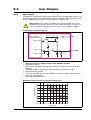
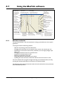
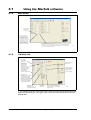
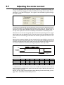
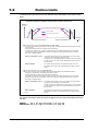
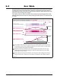
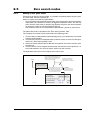
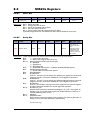
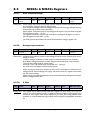
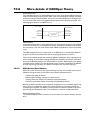
The following illustration shows the timing and motor behaviour when the limit switch
inputs are activated.
Relation between limit switch inputs and the motor behaviour
Velocity
(unsigned)
2
1
= Motor stop after limit switch activation
2
1
= Moving away from the limit switch
Position
Negative Limit switch activated
here when motor moves in
negative direction
Positive Limit switch activated
here when motor moves in
positive direction
-
+
1 When the motor has passed the point where the limit switch is activated the motor is stopped.
The stop may cause an error which is determined by the setting Disable Error on travel limit
(placed at the main tab in MacTalk), which may require an extra procedure before motion of
the motor is possible again.
When not disabled (default):
The motor will stop with an infinitive high deceleration.
The motor will go to passive mode and stay in passive mode.
The error need to be cleared and a mode have to be re-entered
in order to move the motor in the opposite direction away from
the limit point.
When disabled:
The motor will stop. No error is reported and the motor can
immidately be moved in the opposite direction without further
action.
2 When the motor is commanded to move in the opposite direction (away from the limit switch)
the normal acceleration setup is used.
Please notice that if the activated limit switch has caused an error then remember to clear the
error register before the motor can be set back in normal operation.
TT2472-01GB
84
JVL Industri Elektronik A/S - User Manual - Integrated Stepper Motors MIS23x, 34x, 43x