1
CC2430
7
Application examples and RF testing
This section identifies what example software comes with the CC2430 development kit and
also describes how to use the kit for fundamental RF testing.
7.1
Setup
1. Plug two Evaluation Modules into the two Evaluation Boards.
2. Connect antennas to both EM boards
3. Apply power to the Development Kits. See chapter 6.1 for more information about
various ways of powering the Development Kit.
4. Turn on power by setting the power switch correctly.
For a more detailed explanation, see the “Quick Start Instructions” for the development kit in
question.
7.2
Examples
The CC2430 development kit is accompanied by the IEEE 802.15.4 MAC and Z-Stack
software. These together with a corresponding user guide can be downloaded from the Texas
Instruments web site.
7.3
RF testing
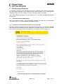
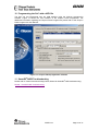
RF testing is best performed by using SmartRF® Studio together with the Development Kit.
Connect the SmartRF04DK to a PC using the USB interface. Start the SmartRF® Studio and
select the SmartRF®04 tab. Select the correct Development Kit (several Development Kits
can be connected to a PC at once), it should be listed as “CC2430 – new device”, and click
the Start button. In the main SmartRF® Studio window settings can be changed, tests
performed and registers adjusted. RF measurement equipment may be connected to the
SMA connector on the EM.
Please see the SmartRF® Studio documentation for more information about the operation of
SmartRF® Studio.
7.3.1
Output power testing
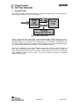
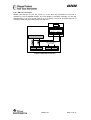
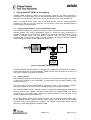
EB+EM
RF carrier
Spectrum analyser
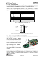
Figure 9: Output power measurement set up
Plug an EM into the SmartRF04DK, and connect the Development Kit to a PC using USB.
Start SmartRF® Studio. Connect the antenna port of the EM board to a spectrum analyser
using a 50-ohm RF coaxial cable. Use the simple TX function in SmartRF® Studio to set up
the RF chip to emit a carrier at the desired frequency. An accurate measure of the output
power can now be made. Enable the “Unmodulated carrier” checkbox to ensure that all the
RF energy is included in the measurement. Using good-quality RF cabling, the loss in the
cabling should be negligible. However make sure that the spectrum analyser is calibrated. If
possible, check it against a calibrated instrument such as an RF signal generator.
Uncalibrated spectrum analysers can display errors of several dBs.
SWRU133
Page 16 of 31