1
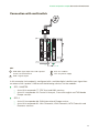
Practical configuration examples/Connection with multiswitch
Configuration of STC-200 modules
Configuration of master STC module
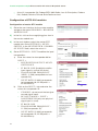
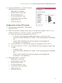
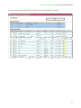
1) Go to the user interface for the master module
and go to the menu HEADEND > HEADEND
MODULE LIST.
2) In the list, click on the magnifying glass icon in the master module row.
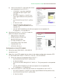
3) In the next window, select the master STC module tab. Go to SETTINGS > LNB/
MULTISWITCH.
4) Identify the LNB local oscillator type (relevant
for the calculation of FI based on the transponder frequency):
a)
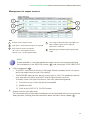
MULTISWITCH, NUMBER OF INPUTS:
select the value “4”.
b) Enter the names and characteristics for
each multiswitch input:
i)
ÌÌ
ÌÌ
SATELLITE: Name of the input signal
to the multiswitch for identification
in subsequent configurations. IKUSI recommends you identify the type of
satellite, polarity and the bandwidth of the signal. In this example, the name of
the satellite is “Astra”, V/H polarities (VERTICAL/HORIZONTAL), H/L band
(HIGH/LOW).
POLARITY: Select VERTICAL (13 V) for the second and third inputs and
HORIZONTAL (18 V) for the other.
BAND: For each polarity select HIGH (22 KHZ) once [INPUT 1 AND 4:
ASTRA HH; INPUT 3: ASTRA VH] and LOW (0 KHZ) [INPUT 2: ASTRA
VL] once.
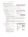
5) Go to the SETTINGS > INPUT menu to define
the input transponders.
a)
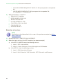
Enter the values of transponder 77 for
INPUT 1:
ÌÌ
ÌÌ
ÌÌ
ÌÌ
18
MULTISWITCH OUTPUT: ASTRA
HH.
FI BAND: HIGH.
TRANSPONDER FREQUENCY
(MHZ): 11 954 (corresponds to transponder 77).
INPUT RATE (KBITS/S): 27 500
(corresponds to transponder 77;
27.5 MSymb/s = 27 500 kBits/s).