1
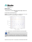
Autolab LED Driver User Manual Current range 1A Conversion factor 1 A/V Multiplier 1 100 mA 100 mA/V 0.1 10 mA 10 mA/V 0.01 1 mA 1 mA/V 0.001 100 µA 100 µA/V 0.0001 10 µA 10 µA/V 0.00001 1 µA 1 µA/V 0.000001 100 nA 100 nA/V 0.0000001 10 nA 10 nA/V 0.00000001 Table 2 – Multiplier factors per current range • Channel Y: this input is used to the measure the AC LED Driver current during the frequency scan. The FRA Y output of the LED Driver is connected to this input. The values from this connection are expressed in V (corresponding to the converted current). The conversion factor is 1 V/A. This signal is therefore specified in A and requires a multiplier of 1. Figure 65 – Setting the parameters for the FRA sampler Note Using the FRA sampler window, it is possible to specify if the time domain information, corresponding to the raw sinewaves recorded by the FRA module, have to be sampled during the measurement1. It is recommended to check both checkboxes for IMPS measurements, in order to verify the quality of the data during the experiments (see Figure 65). 68 | P a g e