1
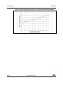
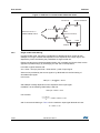
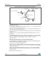
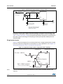
User manual RHF1401 Figure 15. RHF1401 in recommended single-ended mode 2.3V to 2.7V DC value = VREFP/2 AVCC Internal or External VREFP VIN INCM (Internal or External) VINB VREFP/2 VREFM AGND GND External However, we can calculate that the main limitation will come from the Vrefm maximum value = 0.5 V. Let’s take Vrefm = INCM = Vbias = Vinb =0.5 V and Vrefp = 1 V => the input swing allowed on Vin is 1 Vpp centered at 0.5 V => A = 0.5 V Here, CMref = 0.75 V and CMinput maximum = 0.75 V. So for an input voltage Vin from 0 V to 1 V, the output code will vary from 0 to 214. Now, let’s see how much the maximum input amplitude Vin can be to go in saturation mode (bit OR set to 1). As CMref + 0.2 V = 0.95 V, the theoretical input voltage Vin allowed can be: Vin = 0.5 V + 0.9 V sin(t). Here, CMinput maximum = 0.95 V but A + Vbias = 1.4 V and Vbias - A = -0.4 V. The -0.4 V is a problem because only -0.2 V is allowed. Finally, the practical input voltage Vin is: Vin = 0.5 V + 0.7 V sin(t) => CMinput maximum = 0.85 V, A + Vbias = 1.2 V and Vbias - A = -0.2 V. Particular case where Vrefm = 0 V and cannot be changed In some applications, a dual mode can be requested: differential mode and single-ended mode with a preference for differential mode first. Let’s take a typical example for differential mode: Vrefp = 1 V, Vrefm = 0 V, Vbias = INCM = 0.5 V. This safe configuration gives a full scale at 2 Vpp (1 Vpp on each input with Vbias = 0.5 V and A = 0.5 V). Here you can use all digital output codes from 0 to 214. Now let’s go to single-ended mode by keeping Vrefp = 1 V, Vrefm = 0 V, Vbias = INCM = Vinb = 0.5 V. What would be the maximum swing allowed on Vin and what would be the resulting code? So: Full scale = 2 x (Vrefp - Vrefm) = 2 V 20/38 DocID13317 Rev 9