1
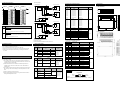
6.2 Wiring example
Motor drive module
2MLF-DV4A/DV8A
2MLF-DV8A
2MLF-DC4A
D/A
conversion
circuit
2MLF-DC8A
①
1㏀~
1㏁
Device
(2MLK)
GND
Motor drive module
*3
②
CH 7
*1
7
8
1㏀~
1㏁
-12V
AGND
②
AGND
External power supply (DC24V) : Pin17~18
CH5 Error
_xy_CH1_ACT
CH1 Active
Uxy.01.2
_xy_CH2_ACT
CH2 Active
Uxy.01.3
_xy_CH3_ACT
CH3 Active
Uxy.01.4
_xy_CH4_ACT
CH4 Active*1
Uxy.01.5
_xy_CH5_ACT
CH5 Active
*1
Uxy.01.6
_xy_CH6_ACT
CH6 Active*1
Uxy.01.7
_xy_CH7_ACT
CH7 Active
Uxy.02
_xy_OUTEN
Output status setting
Uxy.03
_xy_CH0_DATA
Ch0 input
Uxy.04
_xy_CH1_DATA
Ch1 input
Uxy.05
_xy_CH2_DATA
Ch2 input
Uxy.06
_xy_CH3_DATA
Ch3 input
Uxy.07
_xy_CH4_DATA
Ch4 input *1
Uxy.08
_xy_CH5_DATA
Ch5 input
*1
Uxy.09
_xy_CH6_DATA
Ch6 input *1
Uxy.10
_xy_CH7_DATA
Ch7 input *1
*2
*1
Motor drive module
*1
*2
600Ω
or
less
DC 24V
0V
R/W
R
Uxy.01.1
GND
DC/DC
conversion
circuit
_xy_CH5_ERR
Module Ready
+18V
-12V
CH4 Error
Uxy.00.5
CH0 Active
7
8
devices.
_xy_CH4_ERR
_xy_CH0_ACT
600Ω
or
less
17
18
CH3 Error
Uxy.00.4
Uxy.01.0
*3
Analog input terminal, whose respective channels can be connected with external
_xy_CH3_ERR
CH7 Error
CH 7
Terminal
CH2 Error
Uxy.00.3
_xy_RDY
GND
Off: Module error
_xy_CH2_ERR
Uxy.00.F
Description
Blinks: Error occurs (Refer to user’s manual 7.1 for more details)
CH1 Error
Uxy.00.2
0V
1
2
On: Operation normal
CH0 Error
_xy_CH1_ERR
CH6 Error
Motor drive module
Displays the operation status of module
_xy_CH0_ERR
Uxy.00.1
_xy_CH7_ERR
RUN LED
①
Uxy.00.0
_xy_CH6_ERR
CH 0
No.
Description
Uxy.00.7
2MLF-DC4A/DC8A
D/A
conversion
circuit
Global variables
(2MLI)
Uxy.00.6
GND
DC/DC
conversion
circuit
9.1 2MLF-DC4A/DV4A
DC 24V
+18V
17
18
Unit: mm
8.1 Data area
*1
1
2
2MLF-DC4A
CH 0
2MLF-DV4A
9. Dimensions
8. Configuration of internal memory
R
*1
R/W
9.2 2MLF-DC8A/DV8A
R/W
2MLF-DC8A
4. Part names of functions
*1 : Use the cable of 2-core twisted shield.
*2 : 2MLF-DC8A : 550.Ω
8.2 Parameter area (PUT/GET command)
*3 : 2MLF-DV8A/DC8A is available to use from CH0 to CH7.
5. Handling precaution
7. Analog output status
1) Do not drop or give impact on the product.
2) Do not detach PCB from the case, it may cause malfunction.
3) During wiring or other work, do not allow any wire chips get inside the product.
4) Switch off the external power before mounting or removing the module and
the cable.
1) Normal mode
CPU
6.1 Precautions for wiring
Remark
setting
STOP
6. Wiring
Channel
Output status
RUN
Address (2MLK)
Run
Stop
Enable
D/A conversion value
0V or 0㎃
Parameter value
Disable
By parameter setting
0V or 0㎃
0 : Previous output
Enable
By parameter setting
0V or 0㎃
1 : Min. output
Disable
By parameter setting
0V or 0㎃
CPU
Channel
Output status
setting
Remark
Run
Stop
Parameter value
Enable
should be farther than minimum 100mm between both lines in order not to be
By parameter setting
0V or 0㎃
STOP
Disable
By parameter setting
0V or 0㎃
3) Error mode
3) Do not place the cable too close to hot device and material or in direct contact
CPU
Remark
Run
circuit.
causing abnormal operation or defect.
Error
Setting error
(Digital input value)
Error
Setting error
(Parameter)
Details
(2MLI)
R/W
Dec
0H
0
_Fxy_CH_EN
Channel enable
R/W
1H
1
_Fxy_OUT_RANGE
Output range
R/W
2H
2
_Fxy_DATA_TYPE
Input data type
R/W
3H
3
_Fxy_CH0_STAT
CH0 output status
4H
4
_Fxy_CH1_STAT
CH1 output status
5H
5
_Fxy_CH2_STAT
CH2 output status
6H
6
_Fxy_CH3_STAT
CH3 output status
7H
7
_Fxy_CH4_STAT
CH4 output status
*1
8H
8
_Fxy_CH5_STAT
CH5 output status
*1
9H
9
_Fxy_CH6_STAT
CH6 output status
*1
AH
10
_Fxy_CH7_STAT
CH7 output status
*1
BH
11
_Fxy_CH0_ERR
CH0 setting error
CH
12
_Fxy_CH1_ERR
CH1 setting error
DH
13
_Fxy_CH2_ERR
CH2 setting error
EH
14
_Fxy_CH3_ERR
CH3 setting error
FH
15
_Fxy_CH4_ERR
CH4 setting error
10H
16
_Fxy_CH5_ERR
CH5 setting error
11H
17
_Fxy_CH6_ERR
CH6 setting error
12H
18
_Fxy_CH7_ERR
CH7 setting error
*1
Channel
4) Check the polarity when wiring the terminal.
5) Wiring with high-voltage line or power line may produce inductive hindrance
2 : Mid. output
3 : Max.output
allowable current, whose size is not less than the max. cable standard of
with oil for long, which will cause damage or abnormal operation due to short-
0 : Previous output
1 : Min. output
2) Cable shall be selected in due consideration of ambient temperature and
AWG22 (0.3㎟).
3 : Max.output
2) Test mode
1) Do not place AC power line near to the module’s external input signal line. It
affected by noise and magnetic field.
2 : Mid. output
Global variables
Hex
R/W
R
*1
*1
*1
*1
2MLF-DV8A/DC8A only
Stop
Remark
Max or Min
Parameter value
0V or 0㎃
By parameter setting
H/W error
0V or 0㎃
Power-on
0V or 0㎃
How to use U device
0 : Previous output
1 : Min. output
2 : Mid. output
3 : Max.output
Base No.
Slot No.
Uxy.00.0
Bit No.
Word No.
Ex1) When reading “CH0 Active” bit of Base 1, Slot 6 module
-> U16.01.0
Ex2) When reading “CH0 Active” bit of Base 0, Slot 11 module -> U0B.01.0