1
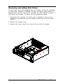
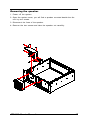
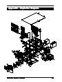
5. Two additional 3.5" drive assemblies are piggybacked on the main drive
bay. The first assembly, directly mounted to the main drive bay, is accessible from the front panel and preferably used for FDD drives. The second
assembly is mounted on the first assembly and is not accessible from the
front panel. To separate the two assemblies remove the 4 screws on the
top of the assemblies and slide them backwards and lift them up to release
them from the main drive bay.
6. Place the 5.25" drive inside the main bay, aligning the screw holes (4 at
both side) in the drive with mounting holes in the housing, inserting screws
to secure the disk drive to the main drive bay. (The first drive bay should
be moved away.) The bottom space is of the main drive bay is for
installation of an additional 3.5" HDD.
7. Install the accessible 3.5" FDD and non-accessible HDD into the two
piggybacked drive assemblies and secure the assemblies to the main
drive bay with the 4 top screws. Make sure that the assemblies hooks are
properly seated.
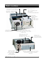
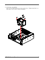
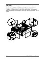
8. If a 10th full-size card
needs to be installed
than omit the installation of the non-accessible HDD bay (2nd
drivebay assembly).
Omitting this drive
creates just enough
space for a full-size
add-on board.
2nd drivebay
for HDD or
10th full-size slot
1st drivebay
exposed, for
FDD/HDD
9. Place the main housing
with drives back into its
previous position inside
the chassis, securing it
with the previously
removed screws.
main drive bay
8
IEC-830 User's Manual