1
Wiring
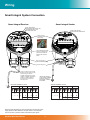
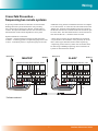
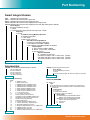
Smart Integral System Connection
Smart Integral Receiver
Smart Integral Sender
Y
HI
FSH
CAL
EN
S
1
2
3
4
5
6
7
8
Green Power ON LED
Red Transmitter enabled LED
Remove Plug-In
terminal block for
easier wiring.
TEST
DELAY
SITIVIT
Green Power/Signal
strength/alignment indicator LED
Blue Calibration/Error LED
Red Relay Status LED
INT 1
9 10
1
2
2
3
MICROWAVE SENDER
3
PRESS
TO TEST
PWR TX
4
5
6
7
8
9 10
The AC earth/ground cable
must be connected to the
ground screw inside the
housing when using AC
power.
Hole for securing of
optional identification tag
M4 grounding screw
If only one cable is used for both
power and output signal, then the
second entry port must be
plugged or blinded. Every Smart
receiver is supplied with two M20
glands (or 3/4”NPT adaptors)
mounted on the unit and one
blind plug loose.
N
L1
8.
9.
10.
6.
5.
10.
4.
L1
9.
3.
N
8.
-
12-30VDC 80-265VAC
12-30VDC 80-265VAC
Terminals 1, 2, 3, 4, 5, 6 not used
Note: AC power terminals may only be used when universal AC power
supply option has been selected - see part numbers - AC terminals
have no function in products without universal AC power option.
Gladiator Microwave Series
2.
-
AC-IN
7.
DC-IN
1.
B
6.
RS 485
SENDER TERMINAL LAYOUT
AC-IN
7.
A
5.
4. Test
NO
3.
1.
2. COM
RECEIVER TERMINAL LAYOUT
COMMS DC-IN
RELAY
NC
**
**Ground the housing to
vessel, if vessel is metallic.
Ground the housing to
plant ground, if vessel is
non-metallic.