1
- Photoelastic Modulators
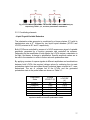
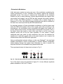
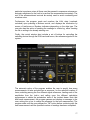
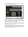
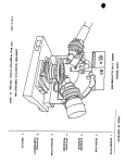
Initial tests were carried out using only one of the modulators, evaluating the
correct performance of both, modulator and detector against the computer
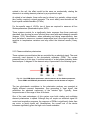
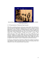
generated curves. The set-up to examine the functionality of the elements
consists on pair of linear polarisers oriented perpendicularly with respect from
one another (null system), and a PEM, fast axis oriented horizontally, between
both of them. The PEM modulation is controlled with a square signal at a
frequency of 47 KHz, with different phase retardances that can be modified by
the users via a control provided by the PEM manufacturer.
An important property of these photoelastic modulators is that the beam must
enter the PEM at the precise centre of the crystal, given that, according to the
manufacturer, the modulation varies sinusoidally throughout the crystal as it
moves away from the centre. This was tested, and proved to be correct. Thus, if
the beam enters the crystal in some other point that is not the centre, the
obtained curves will not be the ones expected. For this reason, a black
cardboard mask was made for both modulators that cover the windows the
crystals are in and with a small orifice in the exact centre so as to ensure the
incident beam enters the PEM at the right point.
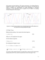
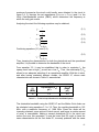
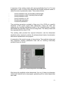
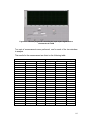
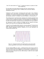
Using a mathematical analysis software, in this case Mathcad™, the ideal light
intensity transmission curves corresponding to several different polarisation
states passing through the system were estimated, in order to predict the
response that was to be obtained during experimental trials.
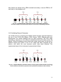
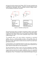
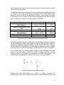
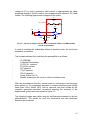
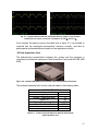
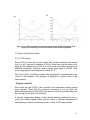
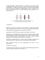
The experimental setup for these tests is shown in Fig. 2.
Fig. 3.2 – Experimental setup used for the characterisation of the photoelastic modulator.
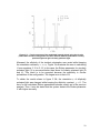
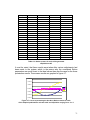
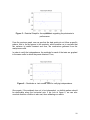
Two of the ideal curves are presented in figure 3.3, for two different amplitude
phase retardations: half- and 1.5-wave.
38