1
MAINTENANCE
For optimum performance and safety, regular tool maintenance is required. The operator maintenance is
limited to the replacement of the drive square and the silencer. All other maintenance and repair should be
carried out by Norbar or a Norbar distributor. Maintenance intervals will depend on the tool usage and the
environment in which it is being used. The maximum recommended maintenance and recalibration interval is
12 months.
TIP:
Steps the operator can take to reduce the amount of maintenance required include:
1. Use the tool in a clean environment.
2. Use an air compressor fitted with a dryer.
3. Ensure the Lubro Control Unit has sufficient hydraulic oil.
4. Ensure the Lubro Control Unit delivers hydraulic oil at the correct rate.
5. Ensure the Lubro Control Unit is regularly maintained, see product handbook.
6. Maintain the correct torque reaction.
Air Lubrication
Add Shell Tellus S2M 32 or equivalent good quality hydraulic oil to the Lubro Control Unit.
Gearbox
Under normal operating conditions it is not necessary to re-grease the gearbox. The gearbox contains
Lubcon Turmogrease Li 802 EP or equivalent good quality grease.
Silencer
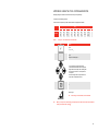
The silencer (part number 18591) must be changed every 12 months. This may be more frequent for high
tool usage or dirty environments.
TIP:
1.
2.
3.
4.
5.
6.
7.
8.
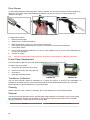
Change silencer with tool upside down, as shown, to ensure internal parts (spring & valve)
are kept in place.
Remove M4 screw (A) (part number 25381.10) using a 2.5mm hexagon key.
Remove pin (B) (part number 26284) using a pin punch.
Pull out air inlet tube (D) with base plate & silencer.
Remove silencer (E) from air inlet tube.
Fit new silencer (part number 18591) over air inlet tube.
Fit air inlet tube assembly (C, D & E) into handle against spring resistance.
Fit pin (B) with a hammer.
Fit screw (A) and torque to 0.5 N·m. Do not over tighten this screw as it is likely to break the base plate
moulding.
TIP:
When refitting air inlet tube assembly into handle care should be taken to ensure correct
alignment between air inlet tube & spring. It may be easier to fit the spring into air inlet tube
first and secure with a small amount of grease.
D
A
B
C
E
FIGURE 14 – Silencer replacement
21