1
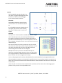
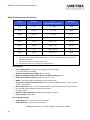
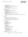
AMETRIX 100 Series Picoammeter Manual SyncBus FOR THE MODEL 101 AND 102 ONLY, the unit offers a programmable digital bus that interfaces to industry standard trigger in/out synchronization schemes. Connector The SyncBus connectors are on the rear chassis and are two standard female DB-‐ 9s. It is a handshaking system whereby units in the system pass control to one another; sort of an “I’m done, now it is your turn” system. Hardware The system can be connected as a Wired And in which multiple unit’s Wired And pins are connected in parallel. When all instruments involved in a function are started, each pulls to ground the same Wired And pin. As each completes its task the pin is released; the signal at the pin rises only when the last unit releases the pin. One must still declare a master unit because only the master unit closes the switch that provides the pull-‐up resistor. If each unit had a permanent pull-‐up resistor, the Wired And load would change as the number of units changed. Multiple instruments can also use the Wired And pins as Voltmeter Complete/Trigger Input pairs. One unit’s Wired And pin is programmed as an output and connects to a Wired And pin on another unit that is programmed an input. Units can be programmed to monitor the Wired And lines and respond with pre-‐programmed actions. The two SyncBus connectors are connected in parallel so that it is easy to daisy chain the connections to other units. The two connectors are identical and it doesn't matter whether one connects to the top one or the bottom. Users who wish to connect to other manufacturer’s products are free to do so but risk damaging their products if they connect to incompatible devices. AMETRIX Instruments LLC | 8361 Tyler Blvd. | Mentor, Ohio 44060 12