1
The Z/Z- (Index channel) is supported and can be used to “home” the motor position, but is not
required. This section assumes the use of the FireBlox Termination board. For wiring encoders
directly to the FireBlox-1 Control Module, see J2 - Digital I/O and Encoder Connector on page 49.
While encoder power (+5VDC) can be derived from the IEEE 1394 network, if several FireBlox-1
Control Modules are used on the same system, it may be necessary to provide this power from
an external supply. External encoder power (AVCC) is connected to the P5 screw terminal on the
Termination Board (when used). When the Termination Board is not used, AVCC is connected
directly to the encoder. An internal fault circuit detects an open, closed or shorted encoder cable
interface and provides fault indication through a status LED and software.
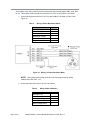
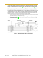
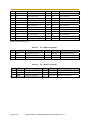
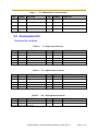
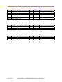
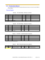
1. Connect the encoder outputs to the Termination Board via the P3 and P4 screw terminals
(P7 and P10 if the 8-pin connectors are used)
2. If external encoder power is provided, set SW2 (on the Termination Board) accordingly
as described in chapter 3 .
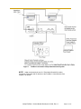
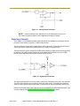
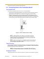
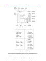
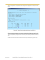
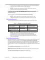
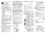
Figure 12. Differential Encoder with Termination Board
Page 20 of 61
Adept FireBlox-1 Control Module Developer’s Guide, Rev. A