1
‘727 Captain’ FLIGHT MANUAL Part II – Aircraft and Systems
DO NOT USE FOR FLIGHT
97
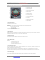
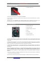
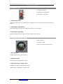
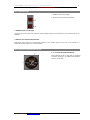
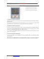
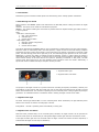
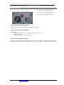
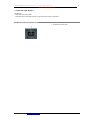
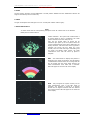
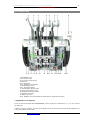
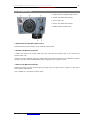
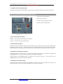
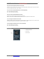
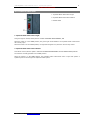
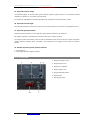
P602. E.L.T. (EMERGENCY LOCATOR TRANSMITTER)
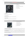
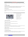
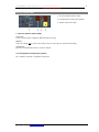
1. E.L.T. (Emergency Locator Transmitter)
Control Switch.
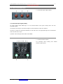
2. LED Light
2. LED Light
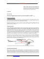
The red LED will illuminate if the switch is turned to on or if the E.L.T. is triggered from an impact.
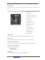
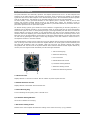
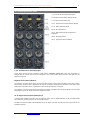
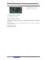
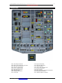
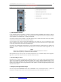
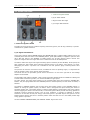
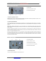
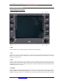
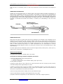
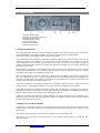
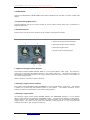
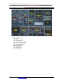
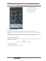
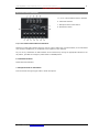
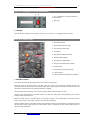
P603. APU CONTROL PANEL
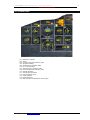
1. APU Master Switch
2. APU Generator Breaker Light
3. APU Generator Field Light
4. Fire Switch
5. APU Generator Breaker Switch
6. Bottle Discharge Switch
7. APU Generator Field Switch
8. Auto Fire Shutdown Arming Switch
9. Switch Guard
10. Fire Warning Test-Reset Switch
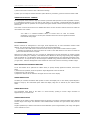
11. APU Ammeter
12. APU Exhaust Gas Temperature Indicator
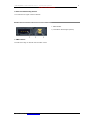
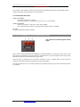
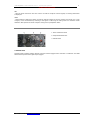
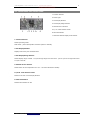
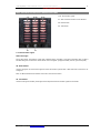
1. APU Master Switch
This switch with OFF--ON--START positions is on the APU control panel.
With this switch in the OFF position, the APU stops as a result of the following automatic actions: the
pneumatic solenoid actuates the 110% speed switch which opens power to the APU fuel solenoid valve and
the bleed air solenoid valve. The generator breaker is tripped.
When the APU engine slows down, the low oil pressure switch closes the APU fuel valve.
With the APU master switch in the OFF position, the APU fire warning and extinguishing system remain
energized from the battery bus.
With the master switch in the ON position, if the battery switch is in the ON position, the APU fuel valve
opens, and if power is on the Nol. 1 DC bus, the APU light illuminates.
With the master switch in the START position and the battery switch in the ON position, the following actions
will take place and the APU will start: the APU starter motor is energized, the APU begins cranking and the
APU crank light illuminates.
© 2010 Captain Sim www.captainsim.com