1
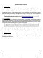
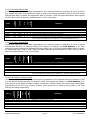
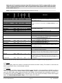
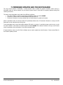
5.7. System Registers
Offset
Address
Size
Type
R/W
Default
These registers are used to configure the serial communication parameters, to reset the device, or to enter the device’s
bootloader mode for firmware updates.
Modbus Address
0x600
41537
16
U
R
1
Serial Baud Rate
Serial Parity Mode
Serial Stop Bits
Serial Response Delay
Serial Commit
Reserved
Reserved
Device Mode
0x601
0x602
0x603
0x604
0x605
0x606
0x607
0x608
41538
41539
41540
41541
41542
41543
41544
41545
16
16
16
16
16
16
16
16
U
U
U
U
U
U
RW
RW
RW
RW
RW
R
R
R
9600
0
1
0
0
0
0
1
Reset to Firmware
0x609
41546
16
U
W
0
Reset to Bootloader
0x60A
41547
16
U
W
0
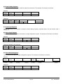
Name
Description
Outputs the device’s Modbus address, as set on the unit’s hardware switch
on the top of the unit. By default, the address is “1”.
Sets the device’s serial parameters. These settings are not applied until a
“1” is written to the Serial Commit register, and are not permanent until a
valid Modbus query message is received using the new settings. See
Configuring Serial Parameters (p. 18).
Reserved for future use. These registers output “0” when read. To ensure
compatibility with future versions, these registers should not be written to.
“1” indicates the device firmware is running normally, “2” indicates the
device is in bootloader mode.
Write the value 0xAA55 (43605) to reboot the unit. This register always
reads as “0”.
Write the value 0xB001 (45057) to reboot the unit. When reset in this
way, the device will enter bootloader mode. This register always reads as
“0”.
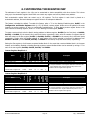
5.7.1. Configuring Serial Parameters
By default, the i-Spy ships pre-configured with the most commonly used serial settings for Modbus products — 9600 baud,
no parity, 8 data bits, 1 stop bit. Generally, there is no need to change this. In addition, it supports a variety of other
baud rates, parity modes, and stop bit modes.
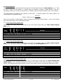
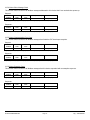
Supported serial settings are listed in the table below.
Parameter
Baud rate
Parity
Stop bits
Default Setting
9600
No Parity (0)
1
Supported Values
9600, 19200, 28800, 38400, 48000, 57600
No Parity (0), Odd Parity (1), Event Parity (2)
1, 2
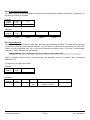
Settings are changed by writing to the corresponding Modbus registers. To change the baud rate, write the new value to
the Serial Baud Rate register 0x601 (41568). For instance, to change the baud rate to 57600, write “57600” to register
0x601. To change the parity mode, write a “0” for no parity, “1” for odd parity, or “2” for even parity into the Serial Parity
Mode register 0x602 (41539). To change the number stop bits, enter “1” for 1 stop bit or “2” for 2 stop bits into the
Serial Stop Bits register 0x603 (41540).
In cases where legacy Modbus master devices cannot process responses fast enough, it may be necessary to enable a
response delay within the i-Spy. If such problems exist, the delay may be introduced by using the Serial Response Delay
register 0x604 (41541). The i-Spy will wait at least as long as specified by this register (in milliseconds) before
responding. Generally, small values between 0 to 100 milliseconds are sufficient. The default value is “0”, meaning that
the i-Spy will respond as soon as its data is ready to reply to the query.
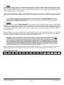
Changes are not applied until a “1” is written to the Serial Commit register. This is to ensure that all serial settings are
applied at once, in case that more than one serial parameter was changed at the same time.
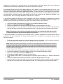
In order to guard against accidental changes to the device’s serial settings and to protect against incorrect or unknown
values, there is a 3-minute period in which the Modbus master device must successfully communicate with the device
before the new settings become permanent. This is to ensure that the Modbus master software or device is capable of
correctly communicating at the new settings. Reading or writing any register, or using any other Modbus function, is
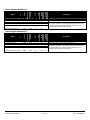
ELKOR TECHNOLOGIES INC.
- Page 18 -
i-Spy – USER MANUAL