1
Stub
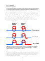
“upper”
P
Stub
“lower”
36 mm
hole
A: Pump
B: Filter
C: Flow meter
Pressure
meter
G: Dose rate meter
H: Spectrometry
I: Pressure
regulator
J: Base stock
injection
K: Acidic stock
injection
D: Electrochemical cell
2
5
6
Blue-marked units in
continuous operation
during
3
2
4
5
3
6
2
1st
guard
2
4
1
5
3
10
6
G
2
4
1
5
H
3
11
6
2
4
6
1
5
3
9
1
F: Circuit to 1st guard
F
8
1
E: Sampling
4
5
D
7
1
3
4
6
4
2
4
3
3
6
5
5
C
6
1
3
4
2
4
6
3
5
3
1
2
6
4
5
B
5
6
2
3
1
6
2
1
1
2
1
A
2
1
1
5
3
12
6
2
4
I
2
4
5
1
6
6
4
5
LTDE Functionality
tests 2005
E
K
External unit
2
External unit
3
1
2
4
6
3
1
5
4
6
5
Inject
Load
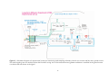
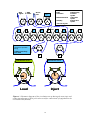
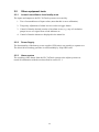
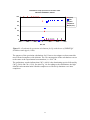
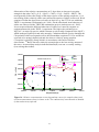
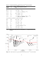
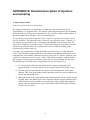
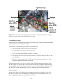
Figure 4. Schematic diagram of the circulation set-up during the tests (top) and
connection diagram of the 6-port valves used for connections of equipment to the
circulation line (bottom).
18
3
13
3
15
J
2
4
5
1
3
14
6
4
5