1
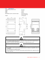
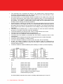
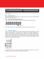
The connecting wire, connecting the device to the outside circuit, should be sized in accordance with local regulations for the maximum amount of the current breaker or other overcurrent protection devices used in the circuit. An external switch or a circuit-breaker should be installed on the supply wires, which will be used to disconnect the meter and the device supplying energy. It is recommended that this switch or circuit-breaker is placed near the meter because that is more convenient for the operator. The switch or circuit-breaker should comply with the specifications of the building’s electrical design and all local regulations. An external fuse or thermal cut-off used as an overcurrent protection device for the meter must be installed on the supply side wires. It’s recommended that this protection device is also placed near the meter for the convenience of the operator. The overcurrent protection device should comply with the specifications of the building’s electrical design and all local regulations. This meter can be installed indoor, or outdoor enclosed in a meter box which is sufficiently protected, in accordance with local codes and regulations. To prevent tampering, an enclosure with a lock or a similar device can be used. The meter has to be installed against a fire resistant wall. The meter has to be installed in a well-ventilated and dry place. The meter has to be installed in a protective box if the meter is exposed to dust or other contaminants. The meter can be installed and used after being tested and can be sealed afterwards. The device can be installed on a 35mm DIN rail. The meter should be installed on a location where the meter can be read easily. In case the meter is installed in an area with frequent surges for example due to thunderstorms, welding machines, inverters etc, the meter is required to be protected with a Surge Protection Device. The device should be sealed immediately after installing it in order to prevent tampering 3P4W 3P3W Connection of the wires should be done in accordance with the connection diagram as shown below: L1 L2 L3 N 18 20 22 24 and and and and 19 21 23 25 phase 1 line in (IN) phase 1 line out (OUT) phase 2 line in (IN) phase 2 line out (OUT) phase 3 line in (IN) phase 3 line out (OUT) Neutral line in (IN) neutral line out (OUT) Forward pulse output contact (S0) Reverse pulse output contact (S0) M-Bus / Modbus communication contact External tariff input (230V) For 3P3W (ARON) connection there must be a bridge made between pin 13 and 17. 10 – Inepro Metering – PRO Series