1
Rev 1/04 - 03
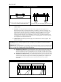
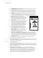
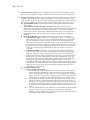
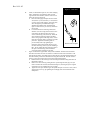
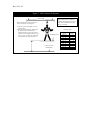
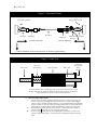
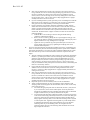
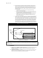
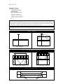
3.2 SYSTEM INSTALLATION: Figure 1, 2 and 3 illustrates a typical safety pole installation. Figure 4
illustrates a typical multi-span installation. The system must be installed and used as specified below.
A.
SYSTEM LOCATION: Install the safety pole system on the working surface level. The poles must be
located at a height according to the clearance requirements in section 3.0 and so the HLL is located
above the workers D-ring at all times to reduce the fall angle and limit the loads on the end anchors. The
poles must be installed at approximately the same elevation. Limit the slope to five degrees or less.
B. SYSTEM DIRECTION: The horizontal line must be installed straight and horizontal, without
turns or bends.
C. APPLICABLE SYSTEM AND BASE LOCATIONS: The system and base location is
determined by reviewing the architectural drawings of the structure. Determine a location that has a
clear passage, without mechanical interference, through to the roof and provides a maximum
working area. If the HLL system will be installed as illustrated in figure 2, location of the bases
should be determined to best meet the fall clearance requirements per the HLL manufacturer’s
instructions.
D. BASE ATTACHMENT: The base may be installed on a concrete floor or on a sub-floor.
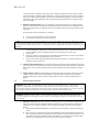
a. CONCRETE FLOORS: If installation is on a concrete floor, 4 each ½ x 4 inch Red-head
anchor bolts will be required or 4 each 3/8 x 4 Simpson TITEN HD anchors, as illustrated in
figure 3a, to maintain the location of the base. Locate the base in the appropriate location.
Drill ½ holes through the four holes located in the base. Set the anchor bolts through the four
base holes and into the concrete. Tighten the nuts on the anchor bolts to secure the base. Take
into account any post-tensioning cables and/or plumbing in the concrete floor when locating
the base by reviewing the approved building plans. Make sure the base is secure before
proceeding.
b. WOOD SUBFLOORS: If attaching to a wood sub-floor, the sub-floor attachment plate
(Section 5), as illustrated in 3b, will be required. Drill holes into the sub-floor so that the 4 x
safety pole j-bolts can be securely anchored to the floor joists. Secure the anchor plate by
tightening the nuts on the j-bolts. Attach the safety pole base (unit 1) to the sub-floor base by
sliding the base over the four threaded posts of the sub-floor attachment plate. Secure the
safety pole base to the sub-floor attachment plate by tightening the 4 nuts provide onto the
threaded posts of the sub-floor attachment plate. Make sure the base is secure before
proceeding. Should the Safety Pole System exceed 32 feet in height, bracing will be required
under the base. A 4 x 6 inch timber brace must be installed directly under the flooring and the
safety pole base. The 4 x 6 inch timber must extend directly under the safety pole base to a
concrete footing or concrete floor.
E. SYSTEM INSTALLATION
a. SINGLE STORY STRUCTURE:
i.
Once the base(s) is securely installed, install the first ten foot section of the safety pole
(Section 2) by lifting and sliding the section onto the base. The pole is fully engaged
when it is upright and fully inserted on the base. It is recommended that the pole be lifted
using two workers or with one worker and a lifting machine such as a fork lift. Beware of
pinching fingers or straining backs when lifting and sliding sections of the safety pole.
ii.
Next on the ground slide the T (Section 4) on to the five foot section (Section 3). Using a
fork lift, raise the two sections using the lifting ring of the five foot section (Section 3)
and slide on to the ten foot section (Section 2). Install the five foot section (section 3) into
the existing ten foot section by sliding the five foot section into the ten foot section. The
five foot section is fully engaged when it is upright and fully inserted into the ten foot
section.
iii.
If you are installing the HLL system, repeat this process of installing the second and third
sections (Section 3 and 4) on the connecting or second safety pole, including the
installation of the side steadying cables. Once the two independent safety poles have been
fully installed you are ready to install the HLLs.