1
Chapter 3 – Signal Box
3.4
Magtrol TMF Torque Flange Transducer
SETTINGS
After all components are connected, the unit can be started up. If the entire measuring system
(TMF and TCU1) is ordered together, all settings are done by Magtrol. If only a TCU1 was ordered,
or a TMF transducer, the system must be adapted.
3.4.1
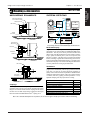
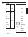
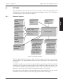
OPERATING PRINCIPLE
Input Md1
Display
RS232
RS422
Input Md2
CPLD – High
Dynamic Frequency
RS422
Microcontroller
Measuring
Input N1
RS422
Input N2
16 Bit D/A Converter
Power Supply
Generator
16 Bit D/A Converter
8 Steps
8 Steps
Low Pass Filter
Low Pass Filter
Analog Output1
Analog Output2
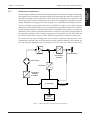
Figure 3–3 Operation Flowchart
The TCU1-SB1 Signal Box generates a voltage in order to supply power to the connected torque
flange transducer. The voltage amplitude can be up to 60 V (peak to peak), with a frequency from
10– 40 kHz.
Four RS422 interfaces serve to receive the signals from the sensing element. The microcontroller
converts the received signals into analog outputs by using CPLDs and 16-Bit D/A converters. The
microcontroller calculates the physical quantity, such as torque and speed, out of the received
frequencies. These values can be shown in the terminal program or on the display.
Each signal box works together with each TMF torque flange transducer. For that, several
characteristic data must be input via a terminal program or the touch screen display.
22
SETUP
RS422