1
Hardware layout and configuration
UM1903
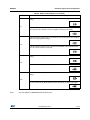
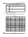
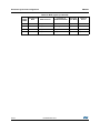
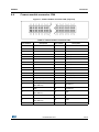
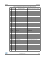
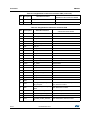
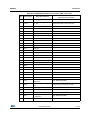
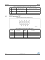
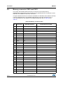
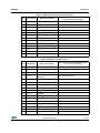
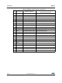
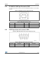
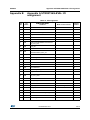
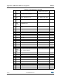
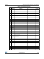
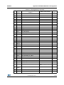
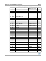
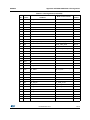
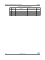
Table 14. LCD modules connector (CN20) (continued)
Note:
Pin No.
Description
Pin connection
Pin No.
Description
Pin connection
11
R4
PJ3
12
G4
PJ11
13
R5
PJ4
14
G5
PK0
15
R6
PJ5
16
G6
PK1
17
R7
PJ6
18
G7
PK2
19
GND
-
20
GND
-
21
B0
PJ12
22
ENB
PK7
23
B1
PJ13
24
-
-
25
B2
PJ14
26
HSYNC
PI12
27
B3
PJ15
28
VSYNC
PI13
29
B4
PK3
30
GND
-
31
B5
PK4
32
CLK
PI14
33
B6
PK5
34
GND
-
35
B7
PK6
36
RESET#
-
37
GND
-
38
I2C1_SDA
PB9
39
INT
MFX GPIO14
40
I2C1_SCL
PB6
41
-
-
42
-
-
43
BL_CTRL
PA8
44
-
-
45
5V
-
46
-
-
47
BLGND
-
48
-
-
49
BLGND
-
50
3.3V
-
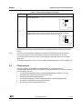
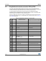
On a 5.7-inch LCD daughterboard, BL_CTRL(PA8) signal adjusts brightness of backlight by
mean of a pulse signal. Since BL_CTRL is shared with MII_MCO, which is in default setting,
SB57 must be removed and SB60 must be closed.
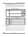
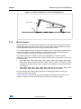
The orientation of the 5.7 inch LCD daughterboard can be changed by hinged standoffs and
pillars. Refer to Figure 5 for details.
26/79
DocID027919 Rev 1