1
Chapter
1
About This Guide
Overview
This guide describes the hardware-specific functionality and usage of the Performance
Technologies’ PCE335 PCI Express® Four-Port WAN Communications Adapter. In these
chapters you will find installation and configuration information, plus a functional block
description intended for the application developer of this board. Here is a brief description of
what you will find in this guide:
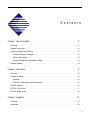
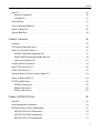
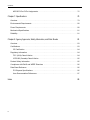
Chapter 1, “About This Guide”, this chapter, provides links to all chapters and appendices in
this guide, plus related documents, customer support and services, and product warranty
information.
Chapter 2, “Introduction,” on page 15 provides a product summary, an overview of product
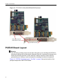
features, and the information about component layout of the board and the cover faceplate.
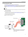
Chapter 3, “Installation,” on page 21 provides information about installing the PCE335, and
replacing the faceplate, as well as information about the PCE335 cables. Additionally, there is a
note about PCI Express slots.
Chapter 4, “Development Environment,” on page 27 provides information about the functional
blocks on the board, the processor, reset logic, memory, interrupt sources, JTAG support, PCI
Express interface, flash memory, user I/O, clock steering, and the user-configurable switches.
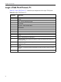
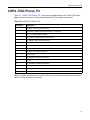
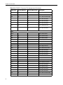
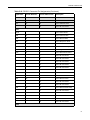
Chapter 5, “Connectors,” on page 39 provides information about the pinouts and connectors on
the PCE335, including: PCI Express connector, serial I/O connectors, console serial port
pinouts, logic and COPS JTAG port pinout, the optional jumper header, and the cable pinouts.
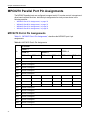
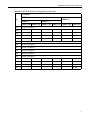
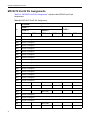
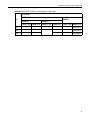
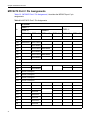
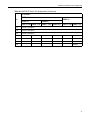
Chapter 6, “MPC8270 I/O Ports,” on page 69 provides information about the two generalpurpose serial management controllers and the four general-purpose parallel I/O ports on the
communications processor module.
11