1
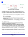
VE2ZAZ’s GPS-DERIVED 10MHz FREQUENCY STANDARD Figure 4: FLL States and Transitions Diagram 3.2.1 Locked The Locked FLL state is encountered during normal “stabilized” operation. While in this state, the FLL provides a 10MHz frequency reference “locked” to the GPS 1 Pulse-per-Second (PPS) signal. The FLL will transition to this state: When in Unlocked state, if the averaged 10MHz frequency is measured to be less than the Locked Limit when compared to nominal (ideal) 10Mhz frequency. When in Holdover state, if the measured 10MHz frequency sample is less than the Locked Limit when compared to nominal (ideal) 10Mhz frequency. The FLL will leave this state when the 10MHz frequency sample is measured to be greater than the Holdover Limit when compared to nominal (ideal) 10Mhz frequency. The Locked limit and Holdover limit are parameters set by the user (see section 6: User commands for more detail). 3.2.2 Holdover The Holdover FLL state is encounter when / while the 10MHz frequency sample is measured to be greater than the Holdover Limit when compared to nominal (ideal) 10Mhz frequency. While in holdover, the FLL retains the last valid DAC setting, which holds a constant tuning voltage on the VCXO. This provides a stable free-running frequency reference, while the FLL waits for a valid 10MHz frequency sample. Note that, while in the holdover state, the reference is no longer “locked” to the GPS 1 Pulse-per-Second (PPS) signal. The FLL will leave the holdover state: USER MANUAL - Version 1.1 13 of 32