1
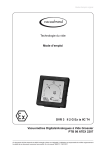
page 1 of 17 Technology for Vacuum Systems Instructions for use DVR 2 Analog/Digital Rough Vacuum Gauge Documents are only to be used and distributed completely and unchanged. It is strictly the users´ responsibility to check carefully the validity of this document with respect to his product. manual-no.: 999001 / 04/04/2012 page 2 of 17 Dear customer, Your VACUUBRAND vacuum gauge shall support you at your work for a long time without any trouble and with full load output. Thanks to our large practical experience we attained much information how you could add to an efficient application and to personal safety. Please read these instructions for use prior to the initial start-up of your controller. VACUUBRAND vacuum gauges are the result of many years of experience in construction and practical operation of these vacuum gauges combined with the latest results in material and manufacturing technology. Our quality maxim is the „zero fault principle“: Every vacuum gauge leaving our company, is tested intensively including an endurance run. Therefore faults, even those which occur rarely, are identified and can be eliminated immediately. The achievement of the specifications after the endurance run is tested for every device. Every VACUUBRAND device achieves the specifications. We are committed to providing our customers with this high quality standard. We know that the device cannot replace all of your real work and hope that our products contribute to an effective and trouble-free realisation of your work. Yours VACUUBRAND GMBH + CO KG After sales service: Contact your local dealer or call +49 9342 808-5500. The document ”Safety information for vacuum equipment” is part of this manual! Read the ”Safety information for vacuum equipment” and observe the instructions contained therein! Trademark index: VACUU•LAN® (US-Reg.No 3,704,401), VACUU•BUS®, VACUU•CONTROLTM, chemistry-HYBRIDTM, Peltronic®, TURBO•MODETM, VARIO®, VARIO-SPTM, VACUUBRAND® (US-Reg.No 3,733,388) and also the shown company logos are trademarks of VACUUBRAND GMBH + CO KG in Germany and/or other countries. Documents are only to be used and distributed completely and unchanged. It is strictly the users´ responsibility to check carefully the validity of this document with respect to his product. manual-no.: 999001 / 04/04/2012 page 3 of 17 Contents Safety information!......................................................................................................4 General information.............................................................................................................................4 Intended use........................................................................................................................................4 Connecting the device ........................................................................................................................4 Operating conditions ..........................................................................................................................5 Safety during operation ......................................................................................................................5 Maintenance and repair ......................................................................................................................5 Technical data..............................................................................................................7 Wetted parts.......................................................................................................................................7 Use and operation.......................................................................................................8 Changing the pressure unit................................................................................................................8 Pressure measurement......................................................................................................................9 Clock symbol......................................................................................................................................9 Adjusting the operating time and the measuring cycle.......................................................................9 Display of the battery‘s discharge status..........................................................................................10 Troubleshooting........................................................................................................10 Readjustment of the vacuum gauge DVR 2............................................................11 Adjustment at atmospheric pressure................................................................................................ 11 Adjustment under vacuum................................................................................................................ 11 Adjustment to a reference pressure.................................................................................................12 Calibration in the factory..........................................................................................12 Replacing the battery................................................................................................13 Notes on return to the factory..................................................................................14 Health and safety clearance form............................................................................15 EC Declaration of Conformity..................................................................................16 ➨ DANGER indicates a hazardous situation which, if not avoided, will result in death or serious injury. ☞ WARNING indicates a hazardous situation which, if not avoided, could result in death or serious injury. • CAUTION indicates a hazardous situation which, if not avoided, could result in minor or moderate injury. NOTICE NOTICE is used to address practices not related to personal injury. Note: The device contains a battery! Remove battery before disposal (see section ”Replacing the battery”) and dispose of battery and device separately and according to regulations. Documents are only to be used and distributed completely and unchanged. It is strictly the users´ responsibility to check carefully the validity of this document with respect to his product. manual-no.: 999001 / 04/04/2012 page 4 of 17 Safety information! General information ☞ Read and comply with this manual before installing or operating the equipment. ☞ Do not use the equipment if it is damaged. NOTICE Remove all packing material, remove the product from its packing-box, remove the protective covers and keep, inspect the equipment. If the equipment is damaged, notify the supplier and the carrier in writing within three days; state the item number of the product together with the order number and the supplier’s invoice number. Retain all packing material for inspection. If the equipment is not used immediately, replace the protective covers. Store the equipment in suitable conditions. Intended use ☞ The device is designed for ambient and gas temperatures at the pressure transducer connection of +10°C to +40°C at continuous operation, up to +80°C for short periods (< 5 minutes) at the pressure transducer. If installing the device into a cabinet or a housing check maximum temperature. Ensure that the maximum permitted gas temperature at the pressure transducer (see ”Technical data”) is not exceeded. NOTICE Use the equipment and all system parts for the intended use only, i.e. for measurement of vacuum in vessels designed for that purpose. Connecting the device ☞ Avoid uncontrolled overpressure (e. g. when connecting to a locked or blocked tubing system). Risk of bursting. ☞Comply with max. permitted ambient and gas temperature (see ”Technical data”) and make sure ventilation is adequate if the equipment is installed in a housing or if ambient temperature is elevated. ☞ Power supply by an internal 9V battery. Do not charge the battery. Do not open the battery. Do not throw the battery into fire. Do not heat over 100°C and do not bring in contact with water. • Comply with maximum permissible pressures at the pressure transducer. See section ”Technical data”. • Connect hoses gas tight at the pressure transducer connection. • Ensure the stability of hose connections. • In case of residues or aggressive or condensable media install a gas washing bottle if necessary. NOTICE Avoid high heat supply (e.g., due to hot process gases). Connect the vacuum gauge to the vacuum application. Position the vacuum gauge and its vacuum line in such a way that condensate cannot flow towards the internal pressure transducer. Documents are only to be used and distributed completely and unchanged. It is strictly the users´ responsibility to check carefully the validity of this document with respect to his product. manual-no.: 999001 / 04/04/2012 page 5 of 17 Allow the equipment to equilibrate to ambient temperature if you bring it from cold environment into a room prior to operation. Notice if there is water condensation on cold surfaces. Comply with all applicable and relevant safety requirements (regulations and guidelines). Implement the required actions and adopt suitable safety measures. The battery is free from mercury and cadmium. Recommended type of battery see section ”Technical data”. When replacing the battery, always mind its correct orientation when inserting it into the battery compartment. When using a battery of a different chemical system (e. g. alkaline), lifetime may be considerably shorter. Because of their lower capacity, the use of rechargeable batteries is not recommended. Operating conditions ➨ The devices are not suitable for applications which involve dangerous or explosive gases or explosive or flammable mixtures. • Ensure that the materials of the equipment’s wetted parts are compatible with the substances in the vacuum system, see section ”Technical data”. Safety during operation ➨ Adopt suitable measures to prevent the release of dangerous, toxic, explosive, corrosive, noxious or polluting fluids, vapours and gases. ☞ Prevent any part of the human body from coming in contact with the vacuum. ☞ Attention: If the pressure is higher than approximately 1060 mbar the pressure reading becomes incorrect (saturation of the pressure transducer). The display flashes. Immediate pressure relief necessary! Risk of bursting! ☞ Use only genuine spare parts and accessories. Otherwise safety and performance of the equipment as well as the electromagnetic compatibility of the equipment might be reduced. Possibly the CE mark becomes void if not using OEM spare parts. NOTICE Electronic equipment is never 100% fail-safe. This may lead to an ill-defined status of the equipment or of other connected devices. Provide protective measures against malfunction and failure. Ensure that in case of failure the device and the vacuum system always will turn into a safe status. Maintenance and repair ➨ Attention: Due to the operation the equipment might be contaminated by harmful or dangerous substances, clean or decontaminate prior to maintenance. Documents are only to be used and distributed completely and unchanged. It is strictly the users´ responsibility to check carefully the validity of this document with respect to his product. manual-no.: 999001 / 04/04/2012 page 6 of 17 NOTICE Ensure that maintenance is done only by suitably trained and supervised technicians. Interior components of the device can only be repaired at the factory. Returned products will not be repaired or calibrated until the completed health and safety clearance form has been received. In order to comply with law (occupational, health and safety regulations, safety at work law and regulations for environmental protection) vacuum pumps, components and measuring instruments returned to the manufacturer can be repaired only when certain procedures (see section ”Notes on return to the factory”) are followed. Documents are only to be used and distributed completely and unchanged. It is strictly the users´ responsibility to check carefully the validity of this document with respect to his product. manual-no.: 999001 / 04/04/2012 page 7 of 17 Technical data Type DVR 2 Measuring principle capacitive, absolute pressure, gas type independent Pressure transducer ceramic diaphragm (alumina), Pressure reading Pressure units Measuring cycle Automatic sleep mode Measuring range (absolute) analogue and digital LCD display mbar, Torr or hPa (selectable) automatic, once in 3s, once in 1s, three times in 1s (factory-set: automatic) operation time: 1-1000 minutes or continuous operation (”On”), (factory-set: 15 minutes) 1080 mbar - 1 mbar (810 Torr - 1 Torr) Maximum permissible pressure at pressure transducer Measurement uncertainty (absolute) after careful adjustment and at constant temperature Temperature coefficient Maximum permissible temperature of gaseous media at pressure transducer 1.5 bar absolute <±1 mbar (0.75 Torr) / ±1 digit <±0.07 mbar/K (0.05 Torr/K) continuous operation: 40°C, for short periods (< 5 minutes): up to 80°C Ambient temperature range (operation) 10°C to +40°C Ambient temperature range (storage) -10°C to +60°C Permitted relative atmospheric moisture during operation (no condensation) 30% to 85% Degree of protection according to IEC 529 Vacuum connection Power supply Internal volume of measurement chamber IP 40 small flange KF DN 16 and screw-in hose nozzle DN 6/10 mm battery 9V Lithium, 1.2 Ah, Ultralife U 9VL 4.23 cm3 (without hose nozzle) Weight approx. Dimensions L x W x H 375 g 115 mm x 115 mm x 66 mm Wetted parts Components Wetted materials Sensor Aluminium oxide ceramic Sensor housing stainless steel Seals chemically resistant fluoroelastomer Vacuum connection / hose nozzle PBT / PPS glass fibre reinforced We reserve the right for technical modification without prior notice! Documents are only to be used and distributed completely and unchanged. It is strictly the users´ responsibility to check carefully the validity of this document with respect to his product. manual-no.: 999001 / 04/04/2012 page 8 of 17 Use and operation Display adjustment mode/ warning symbol automatic sleep mode replace battery/ display of battery capacity Keys ON/OFF key UP/DOWN key MODE key pressure units, selectable The keys are on the rear side of the device underneath the symbols at the front side. Changing the pressure unit + Torr ➨ Switch the vacuum gauge off. ➨ Press ”MODE” key and keep it pressed while switching the DVR 2 on (”ON/OFF” key). ☞The pressure unit as of the last operation (Torr, mbar or hPa) is displayed. ➨ Select the desired pressure unit with the ”UP/DOWN” key. mbar ➨ Press ”ON/OFF” key to confirm the selected pressure unit and to terminate the mode. Documents are only to be used and distributed completely and unchanged. It is strictly the users´ responsibility to check carefully the validity of this document with respect to his product. manual-no.: 999001 / 04/04/2012 page 9 of 17 Pressure measurement Upon switching on, the absolute pressure (total pressure, independent of gas type) ranging from 1 mbar to 1080 mbar is displayed in the selected pressure unit (Torr, mbar or hPa). ☞��������������������������������������������������������� The pressure transducer was adjusted using factory standards. In general, there is no need for readjustment by the user because of the excellent longtime stability (see section ”Readjustment”). Clock symbol ☞The vacuum gauge is equipped with an automatic sleep mode to save battery power when the instrument is not used. When the clock symbol appears on the display, the vacuum gauge will switch off automatically after approx. 1 minute. ➨ Press ”ON/OFF” key. The clock symbol will disappear and the preselected operation time will start again. Adjusting the operating time and the measuring cycle ☞ The time until automatic switching off (operating time) can be set by the user within a range from 1 to 1000 minutes (factory-set: 15 minutes) or continuous operation ”On” can be selected. ➨ Press ”MODE” key to select the time setting mode. ☞ The clock symbol and the currently set operating time in minutes are displayed. ☞The arrow to the right indicates that the time can be increased using ”UP/DOWN” key. ➨ Press ”UP/DOWN” key to increase operating time. To decrease the operating time: ➨ Press ”MODE” key to change the arrow to the left. ➨ Press ”UP/DOWN” key to decrease the operating time. ➨ Press ”ON/OFF” key to confirm. ☞ The device switches to the mode ”Adjusting the measuring cycle”. ☞The measuring cycle can be set to Automatic, 1 measurement in 3s, 1 measurement in 1s and 3 measurements in 1s. Adjusting the measuring cycle: ☞ The measuring cycle as of the last operation (factory-set: ”A”) is displayed. ➨ Press ”UP/DOWN” key to select the measuring cycle: A = Automatic (automatic determination of the measuring cycle; frequent measurement in case of great pressure change), S1 = 1 measurement in 3s, S2 = 1 measurement in 1s, S3 = 3 measurements in 1s. ☞ The flashing of the arrow (only ”S1”, ”S2” or ”S3”) symbolizes the frequency of the pressure measurement). ☞ Press ”MODE” key to change the direction of the adjustment. Documents are only to be used and distributed completely and unchanged. It is strictly the users´ responsibility to check carefully the validity of this document with respect to his product. manual-no.: 999001 / 04/04/2012 page 10 of 17 ➨ Press ”ON/OFF” key to confirm the measuring cycle and to terminate the mode. Display of the battery‘s discharge status When switching off the device, the remaining battery capacity is displayed qualitatively by the number of arrows in the display. ☞ If the battery symbol appears in the display during measurement, the battery should be replaced. ☞ The correct operation of the device is no longer ensured. Troubleshooting Fault Possible cause Remedy ❑ ➨ Automatic sleep mode? ✔ Switch on, increase operating time if necessary. ➨ Battery flat? ✔ Replace battery. ➨ Other cause? ✔ Contact local distributor. ➨ Pressure transducer not correctly adjusted? ✔ Readjust pressure transducer. ➨ Moisture in the pressure transducer? ✔ Dry or evacuate the pressure transducer and readjust if necessary. ➨ Battery flat, battery symbol is displayed? ✔ Replace battery. ➨ Battery flat? ✔ Replace battery. ❑ No display or display disappears. Incorrect pressure reading. ❑ Display is flickering and/ or battery symbol appears. ❑ Adjustment mode cannot ➨ be activated. At the applied pressure, read- ✔ justment is not possible. Admit air to atmospheric pressure or evacuate to a pressure below 20 mbar. ❑ All segments of the LCD ➨ are displayed or no display although battery has been replaced. Pressure transducer or meas- ✔ uring electronics defective? Contact local distributor. Documents are only to be used and distributed completely and unchanged. It is strictly the users´ responsibility to check carefully the validity of this document with respect to his product. manual-no.: 999001 / 04/04/2012 page 11 of 17 Readjustment of the vacuum gauge DVR 2 The equipment has been adjusted at the factory. In general, there is no need for adjustment by the user due to the excellent longtime stability. Depending on operation conditions, type of application and accuracy requirements, an inspection and readjustment may become necessary. Adjustment at atmospheric pressure Admit air to the vacuum gauge. Make sure that the vacuum connection at the vacuum gauge is at atmospheric pressure. Attention: Determine the exact actual atmospheric pressure, e. g. by using an accurate barometer or get accurate reading from the weather service, e. g. at the next airport, etc. (take into account the difference in altitude between e. g. airport and laboratory). + ➨ Press ”UP/DOWN” key and keep it pressed while switching on. ☞ The vacuum gauge switches into the adjustment mode (indicated by a warning triangle). ☞������������������������������������������������ The arrow at the right indicates, that the pressure reading can be increased using ”UP/ DOWN” key. ➨ Press ”UP/DOWN” key to increase the reading to the actual atmospheric pressure. To reduce the reading: ➨ Press ”MODE” key to change the direction of adjustment. The arrow moves to the left indicating that the pressure reading can be reduced. ➨ Press ”UP/DOWN” key to reduce the reading. ➨ Press ”ON/OFF” key to confirm the adjustment and to terminate the adjustment mode. Adjustment under vacuum Evacuate the vacuum gauge to a pressure <0.5 mbar (<0.4 Torr) e. g. by applying a good rotary vane pump. ➨ Press ”UP/DOWN” key and keep it pressed while switching on. ☞ The vacuum gauge switches into the adjust+ ment mode (indicated by a warning triangle). ☞The reading is adjusted automatically to ”zero”. Attention: Adjustment under vacuum with a pressure higher than 0.5 mbar (0.4 Torr) reduces the accuracy of measurement. If the pressure is significantly higher than 0.5 mbar (0.4 Torr), adjustment to a reference pressure is recommended. ➨ Press ”ON/OFF” key to confirm the adjustment and to terminate the adjustment mode. Documents are only to be used and distributed completely and unchanged. It is strictly the users´ responsibility to check carefully the validity of this document with respect to his product. manual-no.: 999001 / 04/04/2012 page 12 of 17 Adjustment to a reference pressure Evacuate the vacuum gauge to an exactly known reference pressure within the range of 0 .... 20 mbar (0 .... 15 Torr). Switch the vacuum gauge to the adjustment mode (see ”Adjustment under vacuum”). ➨ Press ”UP/DOWN” key to adjust the reading from ”0” (”zero”) to the actual reference pressure in the vacuum line in the range of 0 to 20 mbar (0 to 15 Torr). ➨ Press ”ON/OFF” key to confirm the adjustment and to terminate the adjustment mode. Attention: The accuracy of the value of the reference pressure will directly affect the accuracy of the adjustment. If the nominal ultimate vacuum of a diaphragm pump is used as ”reference” vacuum, the accuracy of the adjustment of the vacuum gauge might be doubtful. The diaphragm pump may not achieve the specified value due to condensate, poor state, failure of the valves or the diaphragm. Calibration in the factory Control of measuring equipment The VACUUBRAND DAkkS calibration laboratory is accredited by the Deutsche Akkreditierungsstelle GmbH (national accreditation body of the Federal Republic of Germany) for the measurable variable pressure in the pressure range from 7.5*10-4 Torr to 975 Torr (10-3 mbar to 1300 mbar) in accordance with the general criteria for the operation of testing laboratories defined in the DIN EN ISO/IEC 17025:2000 series of standards (accreditation number D-K-15154-01). The DAkkS is signatory to the multilateral agreements of the European cooperation for Accreditation (EA) and of the International Laboratory Accreditation Cooperation (ILAC) for the mutual recognition of calibration certificates. Rely on calibration in the VACUUBRAND calibration laboratory: - To meet the requirements of the DIN ISO 9000ff and 10012 series of standards regarding the calibration of inspection, measuring and test equipment at specified intervals. - To document that the vacuum gauges calibrated are traceable to national standards of the PTB (Physikalisch-Technische Bundesanstalt; German national institute for science and technology and the highest technical authority of the Federal Republic of Germany for the field of metrology and certain sectors of safety engineering). DAkkS calibration DVR 2.............................................................................................................900217 Documents are only to be used and distributed completely and unchanged. It is strictly the users´ responsibility to check carefully the validity of this document with respect to his product. manual-no.: 999001 / 04/04/2012 page 13 of 17 Replacing the battery Note: Some of the components on the printed circuit board are sensitive to electrostatic discharge. Do not touch components. If necessary, ground the printed circuit board and the person replacing the battery suitably. Attention: Use only a battery of the recommended type (see ”Technical data”). The battery must not be charged or connected to an external voltage. ➨ Unscrew the four countersunk head screws at the rear side of the housing with a Phillips screw driver. ➨ Disassemble the housing parts carefully. Attention: The two housing parts are connected by the sensor cable. printed circuit board battery switch pad ➨ Remove the battery. ➨ Insert the new battery into the battery compartment correctly matching the positive and negative polarity (as shown by the engraving inside the compartment). ☞When reassembling the vacuum gauge, make sure that the switch pad and the printed circuit board are positioned correctly. ➨ Carefully screw both parts of the housing together. Documents are only to be used and distributed completely and unchanged. It is strictly the users´ responsibility to check carefully the validity of this document with respect to his product. manual-no.: 999001 / 04/04/2012 page 14 of 17 Notes on return to the factory Repair - return - DAkkS calibration NOTICE If the measures listed in section ”Troubleshooting” do not work: Return the equipment to the factory for inspection and repair. Interference with the equipment (except replacement of the battery) voids all warranties. Safety and health of our staff, laws and regulations regarding the handling of dangerous goods, occupational health and safety regulations and regulations regarding safe disposal of waste require that for all pumps and other products the “Health and safety clearance form“ must be sent to our office duly completed and signed before any equipment is dispatched to our premises. Fax or post a completed copy of the health and safety clearance form to us in advance. The declaration must arrive before the equipment. Enclose a second completed copy with the product. If the equipment is contaminated you must notify the carrier. No repair / DAkkS calibration is possible unless the correctly completed form is returned. Inevitably, there will be a delay in processing the equipment if information is missing or if this procedure is not obeyed. Eventually, acceptance of the returned equipment will be refused. If the product has come in contact with chemicals, radioactive substances or other substances dangerous to health or environment, the product must be decontaminated prior to sending it back to the factory. To expedite repair and to reduce costs, please enclose a detailed description of the problem and the product’s operation conditions with every product returned for repair. We submit quotations only on request and always at the customer’s expense. If an order is given, the costs incurred are offset from the costs for repair or from the purchase price, if the customer prefers to buy a new product instead of repairing the defective one. ☞ If you do not wish a repair on the basis of our quotation, the equipment might be returned to you disassembled and at your charge! We replace parts due to optical aspects upon your request (at your expense). NOTICE Before returning the equipment ensure that (if applicable): ☞ Equipment has been cleaned and/or decontaminated. ☞ All ports have been sealed. ☞ Equipment has been properly packed, if necessary, please order an original packaging (costs will be charged), marked as appropriate and the carrier has been notified. ☞ Ensure that the completed health and safety clearance form is enclosed. We hope for your understanding for these measures, which are beyond our control. Scrapping and waste disposal: Dispose of the equipment and any components removed from it safely in accordance with all local and national safety and environmental requirements. Particular care must be taken with components which have been contaminated with dangerous substances from the process. Do not incinerate fluoroelastomer seals and O-rings. ☞ You may authorize us to dispose of the equipment at your expense. Documents are only to be used and distributed completely and unchanged. It is strictly the users´ responsibility to check carefully the validity of this document with respect to his product. manual-no.: 999001 / 04/04/2012 page 15 of 17 Health and safety clearance form Devices will not be accepted for any handling before we have received this declaration. Please read and comply with ”Notes on return to the factory”. Oil filled pumps: Drain oil prior to shipping absolutely! 1. Device (Model): ................................................................... 2. Serial no.: ......................................... 3. Reason for return / malfunction: .............................................................................................................................................................. 4. Has the device been used in a copper process step (e.g., semiconductor production). ☐ yes ☐ no 5. Substances (gases, liquids, solids) in contact with the device / which have been pumped: .............................................................................................................................................................. .............................................................................................................................................................. .............................................................................................................................................................. .............................................................................................................................................................. 6. Prior to return to the factory the device has been decontaminated. ☐ yes ☐ no Description of the decontamination method and the test / verification procedure: .............................................................................................................................................................. .............................................................................................................................................................. 7. The device is free of hazardous, harmful substances. ☐ yes ☐ no 8. Protective measures required for VACUUBRAND employees: .............................................................................................................................................................. 9. If the paint is damaged, we wish a repaint or a replacement of parts for reason of appearance (repaint and replacement at customer’s expense). ☐ yes ☐ no 10.Legally binding declaration We assure for the returned device that all substances, which have been in contact with the device are listed in section 5 and that the information is complete and that we have not withheld any information. We declare that all measures - where applicable - have been taken listed in section “Return to the factory”. By our signature below, we acknowledge that we accept liability for any damage caused by providing incomplete or incorrect information and that we shall indemnify VACUUBRAND from any claims as regards damages from third parties. We are aware that as expressed in § 823 BGB (Public Law Code of Germany) we are directly liable for injuries or damages suffered by third parties, particularly VACUUBRAND employees occupied with handling/repairing the product. Shipping of the device must take place according to regulations. Name: ....................................................................... Signature: .............................................................. Job title: .................................................................... Company’s seal: Date: ....................................................................... Release for repair grant by VACUUBRAND (date / signature): .............................................................. VACUUBRAND GMBH + CO KG Tel.: +49 9342 808-5660 Alfred-Zippe-Straße 4 Fax: +49 9342 808-5666 97877 Wertheim, Germany E-Mail: service@vacuubrand.com Documents are only to be used and distributed completely and unchanged. It is strictly the users´ responsibility to check carefully www.vacuubrand.com the validity of this document with respect to his product. manual-no.: 999001 / 04/04/2012 page 16 of 17 EG-Konformitätserklärung EC Declaration of Conformity Déclaration CE de conformité Hersteller / Manufacturer / Fabricant: VACUUBRAND GMBH + CO KG · Alfred-Zippe-Str. 4 · 97877 Wertheim · Germany Hiermit erklärt der Hersteller, dass das Gerät konform ist mit den Bestimmungen der Richtlinie 2004/108/ EG. Hereby the manufacturer declares that the device is in conformity with the directive 2004/108/EC. Par la présente, le fabricant déclare, que le dispositif est conforme à la directive 2004/108/CE. Vakuummessgerät / Vacuum gauge / Vacuomètre Typ / Type / Type: DVR 2 Artikelnummer / Order number / Numéro d‘article: 682902 Seriennummer / Serial number / Numéro de série: Siehe Typenschild / See rating plate / Voir plaque signalétique Angewandte harmonisierte Normen / Harmonized standards applied / Normes harmonisées utilisées: DIN EN 61326-1 Bevollmächtigter für die Zusammenstellung der technischen Unterlagen / Person authorised to compile the technical file / Personne autorisée à constituer le dossier technique: Dr. J. Dirscherl · VACUUBRAND GMBH + CO KG · Alfred-Zippe-Str. 4 · 97877 Wertheim · Germany Wertheim, 04.04.2012 ............................ Ort, Datum / place, date / lieu, date ............................ (Dr. F. Gitmans) Geschäftsführer / Managing director / Gérant ppa. ................................. (Dr. J. Dirscherl) Technischer Leiter / Technical Director / Directeur technique VACUUBRAND GMBH + CO KG Alfred-Zippe-Str. 4 · 97877 Wertheim T +49 9342 808-0 · F +49 9342 808-5555 info@vacuubrand.com www.vacuubrand.com Documents are only to be used and distributed completely and unchanged. It is strictly the users´ responsibility to check carefully the validity of this document with respect to his product. manual-no.: 999001 / 04/04/2012 page 17 of 17 Disclaimer: Our technical literature is only intended to inform our customer. The validity of general empirical values and results obtained under test conditions for specific applications depend on a number of factors beyond our control. It is therefore strictly the users´ responsibility to very carefully check the validity of application to their specific requirements. No claims arising from the information provided in this literature will, consequently, be entertained. VACUUBRAND GMBH + CO KG -Technology for Vacuum Systems- © 2012 VACUUBRAND GMBH + CO KG Printed in Germany Alfred-Zippe-Str. 4 · 97877 Wertheim / Germany T +49 9342 808-0 · F +49 9342 808-5555 info@vacuubrand.com · www.vacuubrand.com Documents are only to be used and distributed completely and unchanged. It is strictly the users´ responsibility to check carefully the validity of this document with respect to his product. manual-no.: 999001 / 04/04/2012