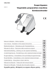
1
Please refer to the numbered drawings
which correspond to the paragraph numbers of the instruction manual.
GB
04/2013
Contents
Introduction
Installation
Use, safety
Cleaning, hygiene
Fault finding
Maintenance
Conformity with regulations
1
1
2
3
3
4
5
Introduction
The User Manual contains useful information for the user on
how to work correctly and in complete safety, and is designed
to make it easier to use the machine (called «machine» or
«appliance» below).
What follows is in no case intended to be a long list of warnings
and constraints, but rather a series of instructions meant to
improve the service provided by the machine in every respect,
and particularly to avoid a series of injuries or damage to equipment that might result from inappropriate procedures for use
and management.
It is essential that all the people responsible for transporting,
installing, commissioning, using, maintaining, repairing or dismantling the machine should consult this manual and read it carefully
before proceeding with the various operations, in order to avoid
any incorrect or inappropriate handling that might be result in
damage to the machine or put people’s safety at risk.
It is just as important that the Manual should always be available
to the operator and it should be kept carefully where the machine
is used ready for easy and immediate consultation in case of any
doubt, or in any case, whenever the need arises.
If after reading the Manual, there are still any doubts concerning
how to use the machine, please do not hesitate to contact the
Manufacturer or approved After Sales Service provider, who
is constantly available to ensure quick and careful service for
improved machine operation and optimum efficiency.
Note that the safety, hygiene and environmental protection standards currently applicable in the country where the machine is
installed must always be applied during all phases of machine
operation. Consequently it is the user’s responsibility to ensure
that the machine is operated and used solely under the optimum
safety conditions laid down for people, animals and property.
Introduction
1.1 DESCRIPTION
E
F
G
H
I
J
K
• The 25 kg angled peeler is used in vegetable preparations (in
restaurants, catering kitchens and small industries) for peeling
potatoes, carrots, turnips, salsifies, celery, etc.
1.1
A
B
C
D
Rear electric housing
Hinged transparent lid
Control support rail
Stainless steel cylinder
Stainless steel angled table
Adjustable feet
Collection tub
Removable filter basket
Vegetable evacuation spout
Hinged handles and door
Water inlet
Installation
2.1 DIMENSIONS - WEIGHT (for information only)
2.1
- Gross weight when packaged :
- Net weight
:
- Dimensions of packaging (L x W x H) :930 x 600 x1580 mm
- Overall dimensions : 880 x 565 x 1425 mm
112 kg
90 kg
2.2 LOCATION
•
•
-
This peeler requires:
A connection to the cold water supply (see §2.3).
An adequate outlet to the drain (see § 2.4).
An electrical power supply (see § 2.5).
This peeler must be mounted on its angled table.
Leave enough space above the machine so that the lid may
be raised, and in front of the table so that the filter basket may
be removed.
- If necessary, block and level the table by unscrewing the lock
screw of the adjustable feet (13 mm socket spanner).
2.2
- Adjust the foot then lock in position.
- Check that the machine is stable.
- We recommend anchoring the table in position to avoid any risk
of it tipping when loaded, by counter drilling the attachment
holes of the feet (8 mm dia. screws max. x 40 mm long and
rawl plugs not supplied).
2.3 CONNECTION TO THE WATER MAINS SYSTEM
• Connect to the water supply by means of a flexible, reinforced
hose of 15 mm diameter, which can withstand the pressure of
the water supply and is sufficiently long enough.
- Carefully connect the hose with two Jubilee clips.
• This peeler uses the pressure of the water mains supply and
a reduced flow rate (approximately 7 litres per minute).
• In conformity with the sanitary regulations, the water inlet
and its stop tap are situated above the top overflow level, at a
standardised distance (overflow device).
2.3a
Note: An electrovalve may be supplied as an option (ask us for
details).
2.3b
Note: As a precaution, a stop tap may be fitted on the wall.
1
TI25 GB 01 07
2.4 EVACUATION OF USED WATER AND SEPARATION OF THE WASTE
• The waste must be separated due to its size (peelings, starch,
moss, soil, etc.).
• Some installations have starch decantation tanks that may be
directly connected. For other installations, this peeler is supplied
as standard on a filter table in order to avoid blockages and bad
smells.
• To connect the machine to the drain, attach the hose (internal
dia. 50 of mm) to the used water tank with its collar (may be
swivelled through 360 °).
• Tips:
To evacuate the used water correctly, avoid:
- vertical drops onto inspection chambers (formation of
foam),
- sharp angles,
- flattened, deformed or narrow pipes,
- counter slopes, or slopes which are not steep enough.
2.5 ELECTRICAL CONNECTION
• Check that the voltage of the electrical system is the same
as that marked on the rating plate and the label on the power
cable.
• The machine must be protected by a differential circuit breaker
and a 16 A fuse per phase (see table).
• The socket must be accessible so that the machine can be
easily unplugged before any work is carried out on it.
Motor characteristics:
2.5a
- Remove the plate.
- Turn the machine over or lie it down.
- Remove the foot assembly by unscrewing the 4 outer
screws.
- Change over the terminal board connecting strips.
- Change the integral plate wire by moving the connection
terminal lug marked as upper voltage P2 (400V) onto that for
the lower voltage P1 (230V).
- Refit the foot assembly.
- Check anti-clockwise rotation
.
B Number of phases (1 single phase - 3 three phase)
C Nominal voltage in Volts (value, range or commutation)
D Frequency (Hertz)
E Nominal power (Watts)
F Nominal current (Amperes)
G Rating of fuse protecting electrical line (Amperes)
H Approximate electrical consumption (KWh)
1) Dual voltage three phase motor
• Provide a single phase wall socket with 3 phases + earth,
rating 20A and a matching watertight plug fitted on the power
supply cable.
2) Single phase motor
• Provide a single phase wall socket with 2 poles + earth,
rating 10/16 A.
• The direction of rotation is set in the factory.
The machine must be earthed.
3) 230V power supply for external controls
The machine is fitted with a 230 volt AC power supply of a
maximum of 2 Amps controlled by the control box, for possible
connection of a solenoid valve.
To PAT test the Electrolux Range of Food Preparation Equipment,
the PCB board needs to be disconnected before any test is done.
This is due to the fact that the boards are fitted with a grounding
diode that can give incorrect result during such a test. Also on
a standard appliance a flash test of 25 amps and up to 3000v is
used but, as you would expect, to use this on equipment, which
has a printed circuit, board would be quite destructive to that
board. We would recommend the use of a PAT tester approved
for computer systems which use a lower rate of amps.
The appliance is perfectly safe and is CE certificated. There are
two ways to get overcome this problem.
· Disconnect the board as instructed and test using test for
PC’s,
· Or install the mixer on a fused spur (no plug) as this takes it
away from being a portable appliance and the PAT test is then
not needed.
The machine must be earthed with a green / yellow wire.
• Check the direction of rotation of the plate fitted to the
machine.
- Press the START button (see § 3.1).
- Visually check the rotation of the plate via the transparent lid. It
should be turning in an anti-clockwise direction (see arrow
on the plate hub or on the top right of the cylinder).
• If the direction of rotation is reversed, change over the two
phase wires on the plug.
• The initial connection is made for a higher voltage:
(e.g. 400 V) For lower voltage supplies.
(e.g. 230 V) proceed as follows:
- Disconnect the machine.
- Refer to the wiring diagram in §6.6.
Use, safety
Any other use than that described in this manual will not be
considered normal by the manufacturer.
3.1 OPERATION - SAFETY
- Respecting the instructions of this manual for the use, cleaning
and maintenance of the machine.
• The safety of the user is ensured by:
- A continuous pressure control system to evacuate the
vegetables when the door is opened.
• Control housing
A,B,E Timer
C STOP button
- The motor stopping when the lid is opened.
- The START button needing to be pressed after stoppage ("no
voltage" release).
D START button
• This peeler operates normally if:
- The door and lid are closed.
- The timer is set to the continuous or timed position.
- The size and design of the waste outlet zone, which avoids
any blockage.
- The angle of the machine, making vegetables and waste easier
to remove.
TI25 GB 05 2012
2
a) Continuous operation
1/ Press and hold key A until — is shown on E.
2/ Start by pressing key D.
3/ Stop by pressing key C.
b) Timed operation:
1/ Press key A or B to select the time on E.
2/ Start by pressing key D.
Note:-To change the time while the timer is running, press key C
then change the setting using key A or B, resume the cycle by
pressing key D.
- The time selected at the beginning of the cycle remains in the
memory.
- To stop the current cycle permanently, press key C twice.
c) Operation by holding the START button in :
- When the door is opened to remove the products.
d) Stopping :
- Press the STOP button C then, open the door or the cover.
3.2 NOMINAL CAPACITIES
Note: The performances vary depending on the nature, shape,
size and condition of the products to be peeled, as well as the
results desired.
• Per operation: bags of 25 kg.
• Hourly output (for information only):
- peeling of potatoes: 400 kg.
3.3 PROCEDURE FOR PEELING
• Loading
- Open the lid.
Note: If the peeler has an electrovalve fitted, the water system
opens and closes automatically at the start and end of the
cycle.
• Unloading
- Place a tray under the outlet chute.
- Close the water inlet stop cock.
- Unlock the door with one hand and press the START button
with the other.
- Open the door completely, ensuring that the vegetables are
channelled out.
- Close the door and programme the next cycle (see § 3.1).
Note: Monitor the peeling carefully when the timer is in the
continuous operation position.
3.3
- Check that the door is locked and the filter basket is in
position.
- Load the products and close the lid.
Note: The products must not be loaded above the front edge of
the cylinder.
Do not overload - Do not pack the products in.
Overloading will damage the quality and speed of the
work.
- Open the water stop cock partially to suit the work to be
performed and check that the flow rate is sufficient.
- Select the cycle time (see § 3.1) and press the START
button.
- At the end of the cycle, the machine will stop automatically.
Do not forget to empty the filter basket when it is full or
after peeling.
3.4 RECOMMENDATIONS FOR USE
•
-
- Peeling times: 1 to 2 minutes for new vegetables (potatoes,
carrots), 2 to 4 minutes for the rest.
To peel vegetables:
The vegetables do not need to be washed before peeling.
Avoid peeling small quantities.
Peel vegetables of the same thickness.
Cut long vegetables (salsifies), tips, tops of carrots.
Do not use the abrasive plate to scrape shellfish.
Cleaning, hygiene
4.1 AFTER USE
- Leave the door ajar in order to ventilate the peeling chamber
and avoid squashing the seal.
- Close the lid and open the water stop cock as far as
possible.
- Operate the peeler for a few seconds to get rid of the remaining
waste and to rinse the inside of the machine.
- The filter basket must be emptied then cleaned under running
water along with the tray.
- Clean the outside of the machine with a damp sponge.
Note: Do not use abrasive detergents which scratch the surfaces,
or chlorine based products which can dull the aluminium.
Fault finding
5.1 THE MACHINE WILL NOT START, CHECK THAT:
• The door and lid are closed.
• The machine is plugged in.
• The timer set on continuous or timed operation. 3.1
If the problem persists, contact the maintenance department of your
dealer.
• The electrical power supply to the socket is correct.
5.2 ABNORMAL NOISES
• Stop the machine.
• Check that the rotating parts are fitted correctly.
• Verify that there are no stones or foreign bodies in the peeling
chamber (risk of jamming and damaging the plate and the
abrasive part of the cylinder).
• If the noise persists and the machine lacks power, check
that:
- the three phase motor is not operating on two phases,
- the belt is not worn (see § 6.1),
- the plate turns freely by hand.
3
TI25 GB 01 07
5.3 IF THE PLATE JAMS ON THE SHAFT
5.3
- Unplug the machine.
- Open the lid.
- Remove the central screw A from the plate with a 13 mm
spanner.
- Remove the handle B.
- Insert the screw A again to lift the plate.
- Tighten the screw in completely.
- Remove the plate.
Note: Clean and lubricate the drive shaft of the machine regularly
with tallow or food grease.
5.4 QUALITY OF THE PEELING
- A worn or clogged abrasive plate (see § 6.2).
- Worn abrasive part of the cylinder.
- Vegetables which are too long, of different sizes or too soft.
• Inadequate, irregular peeling with flats may be caused by:
- Incorrect connection (machine rotating in the opposite direction,
see § 2.5.1).
- Peeling time too short.
If the problem persists, contact the maintenance department
of your dealer.
- Overloading of products (see § 3.3).
Maintenance
6.1 MECHANISM
- Remove the support bracket and remove the belt.
• This peeler only requires a minimum amount of maintenance
(the bearings of the motor and mechanism are greased for life).
• It is recommended that the following be checked at least once
a year:
- the electrical connections.
- the condition of the flexible water inlet hose and its
attachment.
- the wear of the belt.
• Tensioning the belt:
- Fit a new belt, ensuring that it is correctly aligned in the
grooves.
- Fit the support bracket but do not tighten the screws.
- Bring the tensioning screw B until it touches the support
bracket, then tighten by 3 turns with a spanner.
- Tighten the motor retention screws B in position.
6.1
- Check that the belt is tensioned correctly by pressing on one
side of the belt with your index finger.
- Unplug the machine.
- Remove the peeler from the table (4 screws, 13 mm hex.
spanner).
- Turn the machine over or lie it down.
- Unscrew by one turn the 3 screws A retaining the motor (13 mm
hex. spanner).
- Remove the ventilation plate.
- Tension the belt (with the tensioning screw B, 13 mm hex.
spanner).
• Changing the belt:
- Fit the ventilation plate and the peeler on its table.
- Check that the peeler operates correctly.
• Access to electrical components.
- Unplug the machine.
Residual voltage at the capacitor terminals.
• The capacitors may retain an electrical charge. To avoid
taking any risks when carrying out work, we recommend
discharging them by connecting their terminals with an insulated
conductor (e.g. a screwdriver).
6.1
- Completely remove the 3 screws A retaining the motor.
6.2 MAINTENANCE OF THE EQUIPMENT
• ABRASIVE PLATE: Inefficient
- Worn abrasive layer which has revealed the base of the plate
(poor peeling of the vegetables and formation of flats): change
the plate.
- Clogged plate (calcium, starch or soil deposits): brush the
plate. To remove it, see § 5.3.
- Worn abrasive part of the cylinder: replace it.
6.3 ADJUSTING THE SAFETY DEVICES
• Check that the safety devices are operating correctly on a
regular basis:
The motor should stop:
- When the lid is opened.
•
-
When the door is opened.
If either of these two functions does not operate correctly:
Do not use the machine.
Have it adjusted by the maintenance of your dealer.
6.4 CHANGING THE SEAL AND ADJUSTING THE DOOR
- Fit the seal in the groove, ensuring that the joint is in the middle
at the top.
- Finish off by applying a second bead of silicon, ensuring that
you do not apply too much.
• Proceed as follows:
- Pivot the door upwards.
- Remove the old seal, and carefully scrape and clean its
groove.
- Apply a thin bead of silicon sealant in the groove.
TI25 GB 09 97
Leave to dry for 24 hours in the ambient air, leaving the door
closed before use.
4
6.5 CHANGING THE LID SEAL
- Fit the seal in the groove, ensuring that the joint is in the middle
at the back of the lid.
• Proceed as follows:
- Remove the old seal and clean the lid.
Leave to dry for 24 hours in ambient air, with the lid unlocked.
- Apply a bead of silicon sealant in the seal groove.
6.6 ELECTRICAL COMPONENTS
•
-
See electrical diagrams.
•
-
Identification of the colours of the wires:
Power circuit : black
Control circuit : red
Phases
: L1 /L2 / L3
Neutral
: N
Earth
: B/C green and yellow
Identification of the components:
SI : Lid safety device
S2 : Door safety device
S3 : Motor probe
M : Motor
Mi : TImer
CD : Start-up condenser
single phase motor
CP : Permanent condenser
MA : Start-up relay
Y1 : Electrovalve (optional)
}
6.7 ADDRESS FOR SERVICE REQUIREMENTS
We advise you to contact the dealer who sold you the
machine.
Dealer's stamp
For any information or orders for spare parts, specify
the type of machine, its serial number and the electrical
characteristics.
The manufacturer reserves the right to modify and make
improvements to the products without giving prior warning.
Date of purchase .................................
Conformity with regulations
The machine has been designed and manufactured in
conformity with :
- The machine directive 98/37 EEC,
- The CEM directive 2004/108EEC,
- 2011/65/EU Directive on the restriction of the use of certain
hazardous substances
2002/96/CEE « WEEE »
This conformity is certified by:
- The CE conformity mark, attached to the machine.
- The corresponding CE declaration of conformity, associated
with the warranty.
- This instruction manual, which must be given to the
operator.
Acoustic characteristics:
- The acoustic pressure level measured in accordance with the
test code EN ISO 3743.1-EN ISO 3744 (73 dBA).
Protection indices as per the EN 60529-2000 standard:
- IP55 electrical controls.
- IP34 overall machine.
Integrated safety devices
- The machine has been designed and manufactured in compliance with the relevant standards and regulations, mentioned
above.
- Before using the machine, the operator must be trained to use the
machine and informed of any possible residual risks (personnel
training obligation)
Food hygiene:
The machine is made from materials that conform to the following
regulations and standards:
- 1935/2004 EEC materials and objects in contact with
foodstuffs
- EN 601-2004: cast aluminium objects in contact with
foodstuffs
The surfaces of the food area (excluding the abrasive parts) are
smooth and easy to clean. Use detergents that are approved for
food hygiene and respect the instructions for their use.
The symbol «
» on the product indicates that this product
may not be treated as household waste. Instead it shall be
handed over to the applicable collection point for the recycling
of electrical and electronic equipment. By ensuring this product
is disposed of correctly, you will help prevent potential negative
consequences for the environment and human health, which
could otherwise be caused by inappropriate waste handling
of this product. For more detailed information about recycling
of this product, please contact the sales agent or dealer for
your product, your after-sales service, or the appropriate waste
disposal service.
2006/12/CEE“Waste”
The machine is designed so that it does not contribute, or as
little as possible, to increasing the quantity or harmfulness of the
waste and the risks of pollution.
Make sure to observe the recycling conditions.
94/62/CEE“Packaging and packaging waste”
The packaging for the machine is designed so that it does not
contribute, or as little as possible to increasing the quantity or
harmfulness of the waste and the risks of pollution.
Make sure to eliminate the various parts of the packaging in
appropriate recycling centres.
- To the European standards :
EN 60 204-1-2006 electrical equipment of machines,
EN 13208-2000: Vegetable-peeling machines, hygiene and
safety.
5
TI25 GB 04 2013