1
R E PA IR M A NU AL
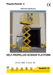
SELF-PROPELLED SCISSOR PLATFORM
Compact 8, 8W, 10 and 12
242 031 8240 - E 05.02
GB
I S O 9 0 01
ARTICULEES
MATS
TELESCOPIQUES
CISEAUX
TRACTEES
L ' A C C E S
A
L ' E S P A C E
PINGUELY HAULOTTE • LA PERONNIERE - BP 9 - 42152 L'HORME • Tél. +33 (0) 4 77 29 24 24 • Fax SAV +33 (0) 4 77 31 28 11
email haulotte@haulotte.com • Web www.haulotte.com
Repair manual
1
GENERAL
This manual gives the information required for you to perform servicing and repair
operations on certain pieces of equipment yourself.
However, we would like to bring your attention to the importance of:
• respecting the safety instructions concerning the machine itself, its use and
its environment,
• use within the limits of its performance,
• correct servicing to ensure long service life.
During and after the guarantee period, our After-Sales service is available to
perform any servicing operations you may require.
In this case, contact our local agency or our Plant After-Sales service, specifying
the exact type of machine and its serial number.
To order consumables or spare parts, use the "Instructions for use and
maintenace" manual and the "Spare parts" catalogue to order original parts, the
only guarantee of interchangability and perfect operation.
REMINDER:We would like to remind you that our machines comply with the
clauses of the "Machines Directive", 89/392/CEE, dated June 14th
1989, modified by directives 91/368/CEE, dated June 21st 1991, 93/
44/CEE, dated June 14th 1993, 93/68/CEE (98/37/CE) dated July
22nd 1993 and 89/336 CEE, dated May 3rd 1989; to directive 2000/
14/CE and directive EMC/89/336/CE.
Caution!
The technical data in this
manual is not binding and we
reserve the right to make
improvements or
modifications without altering
this manual.
1
1
2
Repair manual
Repair Manual
SUMARY
GENERAL .................................................................................................................... 1
1-
GENERAL RECOMMENDATIONS - SAFETY ............................................................ 5
1.1 -
GENERAL WARNING ................................................................................................. 5
1.2 -
GENERAL SAFETY RECOMMENDATIONS .............................................................. 6
1.3 -
RESIDUAL RISKS ....................................................................................................... 8
1.4 -
VERIFICATIONS ......................................................................................................... 8
1.5 -
REPAIRS AND ADJUSTMENTS................................................................................. 9
1.6 -
VERIFICATIONS BEFORE RESTARTING WORK ..................................................... 9
2-
SPECIFICATION........................................................................................................ 11
2.1 -
TECHNICAL CHARACTERISTICS ........................................................................... 12
2.2 -
SIZE........................................................................................................................... 14
2.3 -
TIGHTENING TORQUE ............................................................................................ 16
3-
SAFETY SYSTEMS ................................................................................................... 17
3.1 -
RELAY AND FUSE FUNCTIONS.............................................................................. 17
3.2 -
SAFETY CONTACT FUNCTIONS ............................................................................ 17
4-
WIRING DIAGRAMS.................................................................................................. 19
4.1 -
WIRING DIAGRAM E 501 C...................................................................................... 19
5-
HYDRAULIC DIAGRAMS.......................................................................................... 21
5.1 -
HYDRAULIC DIAGRAM FOR COMPACT 8, 8W AND 10 (B16187) MODELS......... 21
5.2 -
HYDRAULIC DIAGRAM FOR COMPACT 12 (B16188) MODEL .............................. 22
6-
MAINTENANCE ......................................................................................................... 23
i
Repair Manual
6.1 -
GENERAL RECOMMENDATIONS............................................................................ 23
6.2 -
MAINTENANCE DEVICE...........................................................................................23
6.3 -
ELECTRICITY SUPPLY.............................................................................................24
6.4 -
MAINTENANCE PLAN............................................................................................... 25
6.5 -
OPERATIONS............................................................................................................ 27
6.6 -
PRESENCE OF LABELS...........................................................................................28
6.7 -
PRESENCE OF MANUALS ....................................................................................... 35
7-
PREVENTIVE MAINTENANCE SHEETS ..................................................................37
8-
OPERATING INCIDENTS ..........................................................................................47
8.1 -
TABLE OF INCIDENTS .............................................................................................47
8.2 -
FAILURE DETECTION FLOW CHARTS ................................................................... 52
9-
CORRECTIVE MAINTENANCE PROCEDURES.......................................................91
ii
Repair manual
1
1 - GENERAL RECOMMENDATIONS - SAFETY
1.1 -
GENERAL WARNING
1.1.1 - Manual
This manual aims to help maintenance personnel service and repair the machine.
It cannot, however, replace the basic training required by any person working on
the site equipment.
The site manager must inform operators of the recommendations in the
instruction manual. He is also responsible for application of current "user
regulations" in the country of use.
Before operating on the machine, it is essential to be familiar with all the
recommendations in this manual and the user manual to ensure personnel and
equipment safety.
1.1.2 - Labels
Potential dangers and recommendations for the machine are indicated on labels
and plates. Read the instructions on them.
All labels conform to the following colour code:
• Red indicates a potentially fatal danger.
• Orange indicates a danger that may cause serious injury.
• Yellow indicates a danger that may cause material damage or slight injury.
Maintenance pesrsonnel must ensure that these labels and plates are in good
conditions and keep them legible. Spare labels and plates can be supplied by the
manufacturer on request.
1.1.3 - Safety
Ensure that any person entrusted with the machine is take the safety measures
implied by its use.
Avoid any working mode that may affect safety. Any use that does not comply with
the recommendations may generate risks and damage to people and equipment.
After intervention, maintenance personnel must check that the operator manual
is present. This must be kept by the user throughout the machine’s service life,
even if it is loaned, rented or sold.
Ensure that all the plates or labels related to safety and danger are complete and
legible.
Caution!
To attract the reader’s
attention, instructions are
indicated by this
standardised sign.
5
1
1.2 -
Repair manual
GENERAL SAFETY RECOMMENDATIONS
1.2.1 - Operators
Operators must be aged 18 or over and hold an operating permit issued by the
employer after verification of medical aptitude and the practical platform operation
test.
Caution!
Only trained operators may
use Haulotte self-propelled
platforms.
There must be at least two operators present, so that one of them can:
• intervene rapidly if necessary,
• take over the controls in the case of accident or breakdown,
• monitor and prevent machines or people from circulating around the platform,
• guide the platform operator if necessary.
1.2.2 - Environment
Never use the machine:
• On soft, unstable or cluttered floors.
• On a floor with a tilt greater than the allowed limit.
• With a windspeed above the permitted level. In case of outdoor use, check
that windspeed is lower or equal to the permitted level using an anemometer.
• Near electric lines (find out about minimum distances according to current).
In temperatures of less than -15°C (in particular, in cold rooms); consult our
service department if work is required in conditions below -15°C.
• In an explosive atmosphere.
• In an incorrectly ventilated area, as exhaust fumes are toxic.
• During storms (risk of being struck by lightning).
• At night if the machine is not equipped with an optional light.
• In the presence of intense electromagnetic fields (radar, mobile and high
current).
DO NOT DRIVE ON THE PUBLIC HIGHWAY.
1.2.3 - Using the machine
It is important to ensure that in normal use, i.e. platform operation, the platform
station selection key remains in the the platform position to enable control of the
machine from the platform. If a problem occurs on the platform, a person present
and trained in emergency/standby manoeuvres can help by putting the key in the
ground control position.
Never use the machine with:
• a load greater than the nominal load,
• more people than the authorised number,
• lateral force in the platform greater than the level permitted,
• wind speed higher than the permitted level.
6
Repair manual
1
To avoid all risk of serious fall, operators must respect the following instructions:
• Hold the hand rails firmly when climbing onto or operating the platform.
• Wipe any traces of oil or grease off the steps, floor and hand rails.
• Wear protective clothing suited to working conditions and current local legislation, in particular when working in hazardous areas.
• Do not disable the safety system end of stroke contactors.
• Avoid contact with fixed or mobile obstacles.
• Do not increase working height by using ladders or other accessories.
• Never use the hand rails as a means of access for getting onto and off the
platform (use the steps provided on the machine).
• Never climb on the hand rails when the platform is raised.
• Never drive the platform at high speed in narrow or cluttered areas.
• Never use the machine without installing the platform protective bar or closing the safety barrier.
• Never climb on the covers.
Caution!
Never use the platform as a
crane, goods lift or elevator.
Never use the platform or tow
or haul.
To avoid risks of tipping over, operators must respect the following instructions:
• Do not disable the safety system end of stroke contactors.
• Avoid moving the steering control levers in the opposite direction, without
stopping in the "O" position (to stop during a travel manoeuvre, move the
manipulator lever gradually).
• Respect maximum load and maximum number of people authorised on the
platform.
• Distribute the load evenly and place in the centre of the platform if possible.
• Check that the floor resists the pressure and load per wheel.
• Avoid contact with fixed or mobile obstacles.
• Do not drive the platform at high speed in narrow or cluttered areas.
• Do not drive the platform in reverse (inadequate visibility).
• Do not use the machine if the platform is cluttered.
• Do not use the machine with equipment or objects hanging from the hand
rails.
• Do not use the machine with elements that may increase the wind load (e.g.
panels).
• Do not perform machine maintenance operations when the machine is
raised without setting up the required safety means (gantry crane, crane).
• Make daily checks and monitor proper operation during periods of use.
• Preserve the machine from any uncontrolled operation when it is not in service.
NB:
Do not tow the platform (it is not designed to be towed and must be
transported on a trailer).
7
1
1.3 -
Repair manual
RESIDUAL RISKS
1.3.1 - Risks of jolting - tipping over
The risks of jolting or tipping over are high in the following situations:
- sudden action on the control levers,
- platform overload,
- uneven floor (pay attention to thaw periods in winter),
- gusts of wind,
- contact with obstacles on the ground or in the air,
- working on quays, pavements, etc.
Allow sufficient stopping distances:
- 3 metres at high speed,
- 1 metre at low speed.
1.3.2 - Electric risks
Caution!
If the machihe has a 220 V
plug, with max. 16A, the
extension must be connected
to a mains socket protected
by a 30mA differential circuit
breaker.
Electric risks are high in the following situations:
- contact with a live line,
- use during stormy weather.
1.3.3 - Risks of explosion or burning
The risks of explosion or burning are high in the following situations:
- work in an explosive or inflammable atmosphere,
- filling the fuel tank near a naked flame,
- contact with the hot parts of the motor,
- use of a machine with hydraulic leaks.
1.3.4 - Risks of collision
- Risks of crushing people present in the machine’s movement area (travel
or when manoeuvring the equipment).
- The operator must assess any overhead risks before use.
1.4 -
VERIFICATIONS
Comply with current national legislation in the country of use.
In FRANCE: Order dated June 9th 1993 + circular DRT 93-22 dated September
1993, specifying:
1.4.1 - Regular checks
The devices must be regularly inspected every 6 months to detect any defect
liable to cause an accident.
These inspections are to be carried out by an organisation or person specially
appointed by the site manager and under his responsibility (company personnel
or otherwise) Articles R 233-5 and R 233-11 of the Labour Code.
The result of these inspections is recorded in a safety register updated by the site
manager and constantly available to the Works Inspector and the company’s
safety committee, if any, and the list of specially appointed personnel (Article R
233-5 of the Labour Code).
8
Repair manual
1
NB:
This register can be obtained from professional organisations and
for some, from the OPPBTP or private prevention organisations.
The appointed people must be experienced in the field of risk prevention (Article
R 233-11 of decree no. 93-41).
It is forbidden to allow anyone to perform any checks during machine operation
(Article R 233-11 of the Labour Code).
1.4.2 - Examination of device suitability
The manager of the site on which the equipment is used must ensure that the
machine is suitable, i.e. appropriate to the work to be carried out safely and that
it is used in accordance with the instruction manual. Moreover, the French order,
dated June 9th 1993, refers to problems asosciated with rental, examination of
the condition, verifications before starting work after repair, and conditions of
static test coefficient 1.25 and dynamic test coefficient 1.1. All responsible users
should find out about and respect the requirements of this decree.
1.4.3 - Condition
Detect any deterioration liable to cause dangerous situations (safety devices,
load limiters, tilt detector, cylinder leaks, deformation, weld condition, tightness of
bolts, hoses and electric connections, tyre condition, excessive mechanical play).
NB:
1.5 -
In the case of rental, responsible users of the rented machine must
examine the condition and check suitability. They must check with
the rental company that the general regular checks and checks before starting work have been performed.
REPAIRS AND ADJUSTMENTS
Major repairs, interventions or adjustments on the safety systems or elements
(concerning mechanical, hydraulic and electric systems) must be carried out by
PINGUELY-HAULOTTE personnel or personnel working on behalf of
PINGUELY-HAULOTTE, who will only use original spare parts.
Any modification outside PINGUELY-HAULOTTE’s control is unauthorised.
The manufacturer is not responsible if original spare parts are not used or if the
work specified above is not performed by PINGUELY-HAULOTTE approved
personnel.
1.6 -
VERIFICATIONS BEFORE RESTARTING WORK
To be performed after:
• major dismantling-reassembly operations,
• repair of the machine’s essential devices,
• any accident caused by failure of an essential device.
A suitability examination, examination of the condition, static test and dynamic
test must all be carried out (see coefficient paragraph 1.4.2, page 9).
9
1
10
Repair manual
Repair manual
1
2 - SPECIFICATION
Self-propelled platforms, models Compact 8, 8W, 10 and 12, are designed for any
overhead work within the limits of their characteristics (see paragraph 2.1,
page 12) and within the respect of all safety instructions specific to the equipment
and places of use.
The main operating station is on the platform.
The other operating station away from the platform is a standby or emergency
station.
REMINDER:For any information, intervention of spare part requests, please specify the machine type and serial number.
11
1
2.1 -
Repair manual
TECHNICAL CHARACTERISTICS
2.1.1 - Compact 8, Compact 8W technical data
Description
Compact 8
Load (indoor use)
350 kg, including 2 people
450 kg, including 3 people
Load (outdoor use)
120 kg, including 1 person
120 kg, including 1 person
Manual lateral force (indoor use)
40 daN
40 daN
Manual lateral force (outdoor use)
20 daN
20 daN
Maximum wind speed (indoor use)
0 Km/h
0 Km/h
Maximum wind speed (outdoor use)
45 km/h
45 Km/h
Floor height
6.18 m
6.27 m
Working height
8.18 m
8.27 m
Folded length
2.31 m
Folded length with steps
2.42 m
Overall width
0.81 m
1.20 m
Folded height (hand rails)
1.99 m
2.14 m
Folded height (platform)
0.87 m
1.02 m
Wheel base
1.86 mm
Floor clearance
130 mm
Floor clearance with pothole system extended
25 mm
Platform dimension
2.3 m x 0.8 m
2.3 m x 1.2 m
Extension dimension
0.92 m
Extension capacity
150 Kg
Travel speed, machine folded
0/3.5 km/h
Travel speed, machine raised
0/1 km/h
Interior turning radius
0m
0.2 m
Exterior turning radius
2.1 m
2.5 m
Maximum slope during travel
25%
23%
Maximum tilt permitted
2°
3°
Hydraulic tank
Total mass
Max. load on one wheel
Maximum pressure on the floor
25 l
1730 Kg
1950 Kg
1350 daN
6.7 daN/cm
1600 daN
2
7.9daN/cm2
Number of drive wheels
2
2
Number of steering wheels
2
2
Tyres
Non-marking - solid rubber
Wheel diameter
380 mm
Freewheel
YES
Movements
Proportional command
Batteries
24 V - 180 Amp/h C5
24 V - 250 Amp/h C5
200 bars
200 bars
150 bars
165 bars
General hydraulic pressure
Travel
Steering
Lifting
Raising time
37 s
44 s
Lowering time
41 s
56 s
CE standards
12
Compact 8W
YES
Repair manual
1
2.1.2 - Compact 10, Compact 12 technical data
Description
Compact 10
Compact 12
Load (indoor use)
450 kg, including 3 people
300 kg, including 3 people
Load (outdoor use)
120 kg, including 1 person
120 kg, including 1 person
Manual lateral force (indoor use)
40 daN
40 daN
Manual lateral force (outdoor use)
20 daN
20 daN
Maximum wind speed (indoor use)
0 km/h
0 km/h
Maximum wind speed (outdoor use)
45 km/h
45 km/h
Floor height
8.14 m
10 m
10.14 m
12 m
Working height
Folded length
2.31 m
Folded length with steps
2.42 m
Overall width
1.20 m
Folded height (hand rails)
2.26 m
2.38 m
Folded height (platform)
1.14 m
1.26 m
Wheel base
1.86 m
Floor clearance
130 mm
Floor clearance with pothole system extended
25 mm
2.3 m x 1.2 m
Platform dimension
Extension dimension
0.92 m
Extension capacity
150 kg
Travel speed, machine folded
0/3.5 km/h (variable)
Travel speed, machine raised
1 km/h
Interior turning radius
0m
Exterior turning radius
2.5 m
Maximum slope during travel
23%
Maximum tilt permitted
3°
3°
25 litres
Hydraulic tank
Total mass
Max. load on one wheel
Maximum pressure on the floor
2330 kg
2630 kg
1350 daN
7.65 daN/cm
1600 daN
2
10.15 daN/cm 2
Number of drive wheels
2
2
Number of steering wheels
2
2
solid rubber 38 x 13 x 5 cm
Tyres
380 mm
Wheel diameter
Freewheel
YES
Movements
Proportional command
24 V - 250 Amp/h C5
24 V - 250 Amp/h C5
220 bars
220 bars
150 bars
165 bars
240 bars
240 bars
150 bars
150 bars
Raising time
51 s
85 s
Lowering time
42 s
50 s
Batteries
General hydraulic pressure
Travel
Steering
Lifting
CE standards
YES
13
1
2.2 -
Repair manual
SIZE
2.2.1 - Compact 8 size
1.99 m
1.99 m
2.29 m
1.86 m
2.42 m
81 cm
2.2.2 - Compact 8W size
1.19 m
2.14 m
2.29 m
1.86 m
2.42 m
14
1.20 m
Repair manual
1
2.2.3 - Compact 10 size
1.19 m
2.26 m
2.29 m
1.86 m
1.20 m
2.42 m
2.2.4 - Compact 12 size
1.19 m
2.38 m
2.29 m
1.86 m
1.20 m
2.42 m
15
1
2.3 -
Repair manual
TIGHTENING TORQUE
2.3.1 - Tightening torque for large thread
Nominal diameter
Tightening torque in N.M
8.8
10.9
12.9
M 6*1
9 to 11
13 to 14
15 to 17
M 7*1
15 to 19
21 to 24
26 to 28
M 8*1.25
22 to 27
31 to 34
37 to 41
M 10*1.5
43 to 45
61 to 67
73 to 81
M 12*1.75
75 to 94
110 to 120
130 to 140
M 14*2
120 to 150
170 to 190
200 to 220
M 16*2
190 to 230
260 to 290
320 to 350
M 18*2.5
260 to 320
360 to 400
440 to 480
M 20*2.5
370 to 450
520 to 570
620 to 680
M 22*2.5
500 to 620
700 to 770
840 to 930
M 24.3*3
630 to 790
890 to 990
1070 to 1180
M 27*3
930 to 1150
1300 to 1400
1560 to 1730
M 30*3.5
1260 to 1570
1770 to 1960
2200 to 2350
2.3.2 - Tightening torque for fine thread
Nominal diameter
16
Tightening torque in N.M
8.8
10.9
12.9
M 8*1
24 to 29
33 to 37
40 to 44
M 10*1.25
46 to 57
64 to 71
77 to 85
M 12*1.25
83 to 100
120 to 130
140 to 150
M 14*1.5
130 to 160
180 to 200
220 to 240
M 16*1.5
200 to 250
280 to 310
340 to 370
M 18*1.5
290 to 360
410 to 450
490 to 540
M 20*1.5
410 to 510
570 to 630
690 to 760
M 22*1.5
550 to 680
780 to 870
920 to 1000
M 24*1.5
690 to 860
970 to 1070
1160 to 1290
M 27*2
1000 to 1300
1400 to 1560
1690 to 1880
M 30*2
1400 to 1700
1960 to 2180
2350 to 2610
Repair manual
1
3 - SAFETY SYSTEMS
3.1 -
RELAY AND FUSE FUNCTIONS
Reference
FU1
FU2
FU3
FU4
3.2 -
Description
Motor-pump fuse
Speed variator output protective fuse
Speed variator intput protective fuse
Flashing light and working light (optional) protective fuse
SAFETY CONTACT FUNCTIONS
Reference
SB1
SB2
SQ1
SQ3
SQ4
SQ5/6
SQ10
HL1
PT1
Description
Line contactor / Chassis emergency stop button
Platform emergency stop button
Tilt reset position switch
Top position switch
8 meter breaking position switch
Pothole extension
Tilt indicator
Speed variator fault light indicator
Speed variator fault numeric indicator
17
1
18
Repair manual
M1
4
3
250A
6
U1
100
VMNP
B-
B+
FU2
10A
SB1a
10A
100
La PÈronniËre
BP 9
42152 L'HORME
TEL: 04 77 29 24 24
SQ10
FrÈdÈric DENEZE
VERIFIE PAR
30-06-1999
DATE DE VERIFICATION
25-06-1999
9
DATE DE CREATION
HL3
9
DESSINE PAR
HL2
SA4
59
10A
6
10
Laurent DI FLORIO
7
FU4
6
9
9
9
T O N
AU
SA2
11
SP1
SQ1
11
HL5
SQ3
58
HL4
SQ4
SQ5
(4)
SQ6
42
24
36
29
25
26
34
38
(2)
SB2
14
37
8
(1)
13
(7)
C1 B+
C2 B-
Version1
9
(5)
18
HL1
11 10
SM1
11
A9
(6)
A7
11
9
A6
5
4
13
14
1
31
30
6
33
32
23
3
5
B12
U2
GD
6
MDI
B1
3
16
20
indicateur
1
2
PT1
B13
B5
7
HM
19
SB1
E501
YV1
YV2a
YV2b
YV3
IND
c
b
a
YV5a
MODIFICATION
Rajout entrÈe PF/CH
Ajout voyants Trans-Mvt
Modif Cmde YV6
YV9
DATE
18-05-2001
18-07-2000
09-05-2000
YV4
YV5b
VISA
LDF
LDF
LDF
YV6
YV8
U1
21
1
01
NBRE TOTAL DE FOLIOS
SCHEMAS
YV7
17
3
18
19
20
16
6
7
8
9
10
21
B2
B4
B8
C4
SA3
11
17
5
2
16
40
rch
COMPACT 8 - 8W - 10 - 12 OPTIMUM 6 - 8
7
(3)
34
62
SB3
9
15
34
12
27
SA1
40
11
12
HA1
13
4
12
10
Klaxon
PINGUELY-HAULOTTE
GB1
FU1
SB1
(01-10)
FU3
6
U
Libre
M
L
K
J
I
H
G
F
E
D
1
2
3
1
5
C
100
60
39
11
Devers
44
51
RCH
10
MontÈe
Contacteur
61
37
B
220V
12
Descente
MontÈe
16
52
A
14
9
15
PF/CH
17
8
11
Surcharge
18
7
28
Bas
19
GV
20
GV
42
36
> SQ1
21
6
29
38
5
30
Haut
Descente
22
Gauche
50
4
MAV
8 mËtres
Droite
23
3
MAR
Pothole
PV-GV
24
Descente
25
Descente H12S
26
2
31
11
32
33
35
Klaxon
58
41
1
43
Mvt
54
GV
45
Consigne
47
Homme mort
48
Hors neutre
46
Direction
49
4.1 -
27
Repair manual
1
4 - WIRING DIAGRAMS
WIRING DIAGRAM E 501 C
19
1
20
Repair manual
B16187
4
3
YV1
YV2a
YV4
YV3
ESSIEU AVANT
FRONT AXLE
YV6
COMPACT 8W-10
COMPACT 2247E - 2747E
27 L
5
RESERVOIR - TANK
2
220 bar
COMPACT 8 - COMPACT 2032E 200 bar
YV2b
FREIN ESSIEU ARRIERE
REAR AXLE BRAKE
POTHOLES
M
3000W
24V
150 bar
5,5
YV5a
YV9
YV5b
DIRECTION
STEERING
6
1
E
L
V
A
G
IN
T
IF
L
6c
E
G
YV7
6a
6b
5.1 -
5
Repair manual
1
5 - HYDRAULIC DIAGRAMS
HYDRAULIC DIAGRAM FOR COMPACT 8, 8W AND 10 (B16187) MODELS
21
B16188
4
22
3
YV1
YV2a
YV4
YV3
ESSIEU AVANT
FRONT AXLE
YV2b
27 L
5
RESERVOIR - TANK
2
YV6
POTHOLES
YV5a
YV9
YV5b
DIRECTION
STEERING
1
7a
7
6
V
E
L
G
A
L
7c
E
6a
YV7
7d
YV8
G
IN
T
IF
7b
6b
5.2 -
FREIN ESSIEU ARRIERE
REAR AXLE BRAKE
5
1
Repair manual
HYDRAULIC DIAGRAM FOR COMPACT 12 (B16188) MODEL
Repair manual
1
6 - MAINTENANCE
6.1 -
GENERAL RECOMMENDATIONS
Caution!
Do not use the machine as a
welding earth.
Do not weld without
disconnecting the (+) and (-)
battery terminals.
Do not start other vehicles
with the batteries connected.
Servicing oprations described in this manual are given for normal conditions of
use.
In difficult conditions: extreme temperatures, high hygrometry, polluted
atmosphere, high altitude, etc., certain operations must be carried out more
frequently and specific precautions must be taken: consult the PINGUELY
HAULOTTE After-Sales Service for information.
Only authorised and competent personnel may operate on the machine and must
comply with the safety instructions related to Personnel and Environment
protection.
Regularly check that the safety systems work properly:
1°) Tilt: buzzer + stop (travel and lifting disabled).
2°) Platform overload - load.
6.2 -
MAINTENANCE DEVICE
The maintenance stand enables the operator to work under the machine in total
safety.
Instructions: for the COMPACT 8, 8W (see:Photo 1, page 23)
Installing the maintenance stand:
Photo 1
•
•
•
•
•
Position the elevation platform on a firm, horizontal floor.
Ensure that the two emergency stop buttons are "ON".
Turn the chassis ignition key to the "Chassis" position.
Move the chassis lifting switch up to raise the platform.
Turn the maintenance stand forwards and allow to hang vertically on the
lower axle pivot tube.
• Push the lifting switch down to gradually lower the platform until the maintenance stand comes up against the lower pivot tube.
Removing the maintenance stand:
Photo 2
• Push the chassis lifting switch up and gradually lift the platform until the
maintenance stand is free of the lower pivot tube.
• Turn the maintenance stand towards the back to bring it into its storage position on the cylinder fixture.
• Push the chassis lifting switch down and lower the platform completely.
23
1
Repair manual
Operating instructions: for the COMPACT 10, 12 (see: Photo 2, page 23)
These operations are to be carried out on both sides of the platform.
Putting the maintenance stand into place:
•
•
•
•
•
•
Position the platform on a firm, horizontal floor.
Ensure that the two emergency stop buttons are "ON".
Turn the chassis ignition key to the "Chassis" position.
Push the chassis lifting switch up to raise the platform.
Unscrew and turn the maintenance stand and allow to hang vertically.
Push the lifting switch down to lower the platform gradually until the maintenance stand comes up against the two fixing points (top and bottom).
Removing the maintenance stand:
• Push the chassis lifting switch up and gradually raise the platform until the
maintenance stand is free.
• Turn the maintenance stand until it comes into its storage position and screw
back into place.
• Push the chassis lifting switch down and lower the platform completely.
6.3 -
ELECTRICITY SUPPLY
Photo 3
Operating instructions:
Cutting off the electricity supply:
Press the chassis emergency stop.
Starting the electricity supply:
Reset the emergency stop.
24
Repair manual
6.4 -
1
MAINTENANCE PLAN
The plan (overleaf) indicates frequency, servicing points (device) and the
consumables to be used.
• The reference in the symbol indicates the servicing point according to the
frequency.
• The symbol represents the consumable to be used (or the operation to be
performed).
6.4.1 - Consumables
Consumable
Specification
Symbol
Lubricants used by
Pinguely-Haulotte
Gearbox oil
SAE 15W40
SHELL
RIMULA - X
Hydraulic oil
AFNOR 48602
ISO VG 46
BP
SHF ZS 46
Organic hydraulic oil
(optional)
ELF
TOTAL
HYDRELF
DS 46
EQUIVIS
ZS 46
ISO BIO 46
Lithium grease
ISO-XM-2
CARDREXA
DC1
Lithium grease
ENS / EP 700
EPEXA 2
Lead-free grease
Grade 2 or 3
ESSO
GP GREASE
Multimotive 2
Multis
EP 2
Exchange or specific
operation
25
1
Repair manual
6.4.2 - Maintenance diagram
1
10
7
11
8
12
10
12
50
2
3
14
250
500
17
16
1 000
18
2 000
4
12
11
9
5
2
10
6
10
3
250
12
50
500
1 000
2 000
19
26
3 000
Repair manual
6.5 -
1
OPERATIONS
6.5.1 - Summary table
FREQUENCY
OPERATIONS
•
Every day or before
each start of operation
•
•
Every 50 hours
Check the levels:
- hydraulic oil (see paragraph 7 -, sheet P001 ),
- electric batteries
- battery charge, using the indicator
Check cleanliness:
- machine (in particular, check the tightness of connections and
hoses), also check the condition of tyres, cables and all
accessories and equipment.
- platform slide for extension
Check hydraulic oil filter clogging.
REF
1
4
5
6
7
Pay attention for the first 50 hours:
• Change the hydraulic oil cartridge (see 250 hours frequency).
• Check the condition of battery cables (replace if worn)
• Check the tightness:
- screws in general
- front motor fixing screw 9 daNm
- rear brake fixing screws 9 daNm
- wheel nuts (torque 110 daNm)
10
11
12
•
Change the hydraulic filter cartridge (see
paragraph 7 -,
sheet P002 )
Grease:
- steering wheel pivots (see paragraph 7 -, sheet P003 )
- the friction parts of the slides with a spatula (see paragraph 7 , sheet P004 )
Check:
- battery charger connection
- battery level
13
•
Every 250 hours
•
8
9
2
3
14
15
Every 500 hours or
every 6 months
•
If using organic hydraulic oil, empty the hydraulic tank.
16
Every 1000 hours or
every year
•
•
Empty the hydraulic oil tank
Clean the motor pump set carbon
16
17
Every 2000 hours
•
Empty the hydraulic tank and whole hydraulic circuit.
18
•
Check:
- condition of the slides
- condition of the electric cables, hydraulic hoses, etc.
19
20
Every 3000 hours or
every 4 years
REMINDER:All these frequencies must be reduced if working in difficult conditions (consult After-Sales if necessary).
27
1
6.6 -
Repair manual
PRESENCE OF LABELS
It is important to check that the labels and plates warning personnel of the various
dangers associated with using the machine are in good condition.
The labels providing operators with information on machine use and maintenance
must also be checked.
An illegible label may lead to incorrect or dangerous use of the machine.
Operating instructions:
Check the presence of the labels:
Check that all the labels described below are legible and in the correct place.
Replace if necessary (spare parts can be supplied on request, if necessary).
6.6.1 - Common "yellow" labels
23
17
24
9
a
10
18
STOP
3 s
PENDANT LA DESCENTE,
3 SECONDES D'ARRET
AUTOMATIQUE SONT
NECESSAIRES AFIN DE SUPPRIMER LES RISQUES D'ECRASEMENT
7814 464
28
14
Repair manual
1
6.6.2 - Common "orange" labels
16
12
13
a
29
1
Repair manual
6.6.3 - Common "red" labels
3
19
8
1
20
15
7
6.6.4 - Other common labels
22
6
a
25
21
30
Repair manual
1
6.6.5 - Labels specific to the different models
6.6.5.1 - Compact 8
4
6.6.5.2 - Compact 8W
4a
6.6.5.3 - Compact 10
4b
6.6.5.4 - Compact 12
4c
31
1
Repair manual
6.6.6 - Specific labels: Holland
27
24
7814 573 a
6.6.7 - Specific labels: Australia
28
DANGER
BEWARE OF OVERHEAD ELECTRICAL HAZARDS
REGULATION 133A of the CONSTRUCTION SAFETY ACT 1912 REQUIRES
a. Minimum approach of an appliance 3 m for voltages up to 132,000
to live electrical apparatus.
6 m for voltages above 132,000 and up to 330,000
b. Inspection of the work site for 8 m for voltages above 330,000
electrical hazards before commencing to use the appliance.
c. Constant vigilance and an observer required whilst working or travelling the appliance in the vicinity of live electrical apparatus.
32
29
15
Repair manual
1
6.6.8 - Machine label references
Ref
Code
Qty
Description
1
3078145080
4
Risk of crushing upper limbs (hands, fingers, etc.)
2
3078145120
2
"Compact 8" sticker
2
3078145130
2
"Compact 8W" sticker
2
3078145140
2
"Compact 10" sticker
2
3078145150
2
"Compact 12" sticker
3
3078143800
2
Risk of crushing: do not stop in the machine’s working area
4
3078144590
1
Floor height + load capacity 8
4a
3078144600
1
Floor height + load capacity 8W
4b
3078144610
1
Floor height + load capacity 10
4c
3078144620
1
Floor height + load capacity 12
6
3078143688
1
See user manual
7
3078145100
1
DANGER: travel direction
8
3078143810
1
Risk of electrocution: This machine is not insulated.
9
3078144630
1
Risk of deterioration: Do not use the machine while batteries are
charging
10
3078144640
1
Stop time during lowering (French)
10
3078144720
1
Stop time during lowering (Spanish)
10
3078144700
1
Stop time during lowering (German)
10
3078144710
1
Stop time during lowering (English)
10
3078144730
1
Stop time during lowering (Italian)
10
3078144740
1
Stop time during lowering (Dutch)
11
1250127590
2
"HAULOTTE" logo
12
3078145110
4
Information: anchoring hook position
13
3078143830
4
Information: fork-lift truck position
14
3078144680
1
Operating instructions: Freewheel - Brake release
15
3078144670
2
Risk of crushing: Foot crushing (Pothole)
15
3078146700
2
Risk of crushing: Foot crushing (Pothole) (Australia)
16
3078143420
1
Information: Operating instructions (French)
16
3078143430
1
Information: Operating instructions (Spanish)
16
3078143440
1
Information: Operating instructions (German)
16
3078143450
1
Information: Operating instructions (English)
16
3078143460
1
Information: Operating instructions (Italian)
16
3078143470
1
Information: Operating instructions (Dutch)
16
3078144580
1
Information: Electricity operating instructions (Australia)
16
3078144940
1
Information: Operating instructions (Danish)
17
3078143510
1
Risk of deterioration :Battery servicing
18
3078144650
1
Risk of tipping over: Check tilt
19
3078143610
1
Risk of injury: Wear protective clothing
20
3078145310
1
Risk of tipping over: Lock battery rack
21
3078145060
1
Information: Bottom control panel label
33
1
Repair manual
Ref
Code
Qty
Description
22
3078146090
1
Information: Platform control panel label
23
3078143600
1
Risk of electrocution: Do not use as a welding earth. Do not wash.
24
3078143540
1
Information: 220V plug
24
3078145730
1
Information: 240V plug (Holland)
25
3078143520
1
Information: Hydraulic oil
26
146014033
1
Information: 220V plug
27
3078145710
2
Load capacity on extension (Holland)
28
3078144430
1
Danger: Electrocution (Australia)
29
3078144370
4
Sling characteristics (Australia)
6.6.9 - Label positioning on the machine
4
9
10
6
22
7
8
24
27
3
11
2
1
1
21
3
12
13
34
28
25 15 14
3
2
30
23
13
20
12
29
17
18
19
12
26 31
Repair manual
6.7 -
1
PRESENCE OF MANUALS
It is important to ensure that the manuals supplied with the machine are in good
condition and stored in the document holder provided on the platform.
An illegible manual may lead to incorrect or dangerous use of the machine.
Operating instructions:
Check presence of manuals:
Check that all the manuals are legible, complete and stored in the document
holder provided on the platform. Replace if necessary (extra copies can be
supplied on request by the manufacturer).
35
1
36
Repair manual
Repair manual
1
7 - PREVENTIVE MAINTENANCE SHEETS
List of preventive maintenance sheets:
Sheet no.
Description
P001
P002
Checking - filling the hydraulic oil tank
Replacing the hydraulic filter cartridge
P003
P004
Greasing the steering wheel pivots
Greasing the slides
37
1
38
Repair manual
PREVENTIVE MAINTENANCE SHEET
SHEET P001
CHECKING THE HYDRAULIC OIL TANK LEVEL
Sheet 1/1
1 - Preliminary operations
•
Caution !
Ensure that oil temperature
is not too high.
Put the machine in the low position and maintenance configuration (see
§ 6.2, page 21).
NOTA :
•
Do not use the maintenance stands, leave the platform in the low position.
Cut off the electric power supply (see § 6.3, page 22).
2 - Checking the hydraulic oil tank level
•
•
Ensure that the oil level in the tank is sufficient.
Top up if necessary.
NOTA :
•
MAX
MIN
OIL LEVEL
Only use the oil recommended by the manufacturer.
Put the machine back into operational configuration.
PREVENTIVE MAINTENANCE SHEET
PREVENTIVE MAINTENANCE SHEET
SHEET P002
Sheet 1/1
REPLACING THE HYDRAULIC FILTER CARTRIDGE
1 - Preliminary operations
Caution !
Ensure that oil temperature
is not too high.
•Put the machine in the maintenance configuration (see § 6.2, page 21).
•Cut off the electric power supply (see § 6.3, page 22).
2 - Replacing the hydraulic filter cartridge
•Unscrew the body and remove the hydrualic filter cartridge.
•Screw a new cartridge into place.
•Put the machine back into the operational configuration.
PREVENTIVE MAINTENANCE SHEET
PREVENTIVE MAINTENANCE SHEET
SHEET P003
Sheet 1/1
GREASING THE STEERING WHEEL PIVOTS
1 - Greasing the steering wheel pivots
•Cut off the electric power supply (see § 6.3, page 22).
•Grease the pivots.
NOTA :
Only use the grease recommended by the manufacturer.
•Put the machine back into the operational configuration.
PREVENTIVE MAINTENANCE SHEET
PREVENTIVE MAINTENANCE SHEET
SHEET P004
Sheet 1/1
GREASING THE SLIDES
1 - Preliminary operations
•Put the machine in the maintenance configuration (see § 6.2, page 21).
•Cut off the electric power supply (see § 6.3, page 22).
2 - Greasing the slides
•Grease the slides using a spatula.
NOTA :
Only use the grease recommended by the manufacturer.
•Put the machine back into the operational configuration.
PREVENTIVE MAINTENANCE SHEET
Repair manual
1
8 - OPERATING INCIDENTS
8.1 -
TABLE OF INCIDENTS
Before anything else, check that:
• the batteries are charged; the green light indicators should be on.
• the two "palm button" emergency stops on the chassis control box and on
the platform control box are unlocked.
• the oil level in the tank is OK.
Caution!
Bubbles + pressure + heat =
unacceptable situation.
Risk of explosion
NB:
Cavitation (emulsified oil) may cause incorrect operation of hydraulic
components. It takes approximately 4 hours for oil that has been
emulsified under the effects of cavitation to get back to its normal
condition.
8.1.1 - General operation
ANOMALY
CHECK
PROBABLE CAUSE
SOLUTION
Defective batteries
Oil level low
Defective fuses
Defective chassis emergency stop
Defective platform emergency stop
Defective wiring harness
Defective motorpump set
Defective printed circuit
Defective control unit
SHEET DP007
No movement
•
•
•
•
•
•
•
•
•
Hydraulic pump noisy
• Insufficient oil in the tank
• Defective pump
SHEET DP009
Pothole system does
not extend when the
platform is raised
•
•
•
•
•
Defective speed variator
Defective wiring harness
Defective electrovalve YV6 coil
Defective electrovalve YV6
Defective pothole cylinders
SHEET DP013
No movement from the
platform control station
•
•
•
•
•
Defective key switch SA1
Defective electric wiring harness
Defective speed variator
Defective manipulator
Defective printer circuit U2
SHEET DP014
Hydraulic pump
cavitation
(Vacuum in the pump
due to insufficient oil).
The hydraulic oil
becomes cloudy
and white (with
bubbles)
• Oil viscosity too high
• Empty the circuit and
refill with the recommended oil.
47
1
ANOMALY
CHECK
PROBABLE CAUSE
• Oil viscosity too high
Overheating of the
hydraulic circuit
• Insufficient hydraulic oil in the tank
• The hydraulic oil is not at optimum
operating temperature
The system works
irregularly
Repair manual
SOLUTION
• Empty the circuit and
replace with the recommended oil. Top
up with oil as necessary.
• Make some movements without load to
enable the oil to heat
up
8.1.2 - Platform lifting system
ANOMALY
CHECK
PROBABLE CAUSE
SOLUTION
Defective wiring harness
Defective printed circuit U2
Defective manipulator
Defective platform emergency stop
button
SHEET DP001
No up or down
movement from the
platform control
•
•
•
•
No up or down
movement from the
chassis control
• Defective key switch
• Defective wire no. 10
• Defective switch SA2
SHEET DP002
•
•
•
•
•
•
•
•
•
Hydraulic leak
Defective wiring harness
Defective electrovalve YV1 coil
Defective lifting cylinder
Defective electrovalve YV1
Defective or badly adjusted limiter
Defective tilt detector
Defective speed variator
Defective end of stroke contactor
SHEET DP003
No down movement
from the platform or
chassis controls
• Defective wiring harness
• Badly adjusted or defective pressure
contact SP1
• Defective electrovalve YV7 coil
• Defective electrovalve YV7
• Defective speed variator
SHEET DP004
The platform (above
1.5m) comes down
slowly by platform or
chassis controls
• Defective electrovalve YV8 or YV9
coil
• Defective electrovalve YV8 or YV9
• Defective electric wiring harness
• Defective speed variator
SHEET DP005
No up movement from
the chassis or platform
controls
The platform moves up
and down with a jerky
movement
48
• Insufficient oil in the hydraulic circuit
• Top up with oil as necessary
Repair manual
1
8.1.3 - Travel system
ANOMALY
CHECK
PROBABLE CAUSE
SOLUTION
No movement available
Defective pothole cylinder
Defective wiring harness
Defective pothole end of stroke contactor
• Defective brake
• Defective motor
SHEET DP006
No travel in one
direction, FORWARD
or BACKWARD
• Defective speed variator
• Defective wiring harness
• Defective YV2a or YV2b coil
SHEET DP010
High speed
unavailable below
1.5m
• Defective electrovalve YV3 or YV4
coil
• Defective electrovalve YV3 or YV4
• Defective wiring harness
• Defective printed circuit U2
• Defective speed selector switch SA3
SHEET DP011
Only micro-speed is
available below 1.5m
• Defective speed variator
• Defective electric wiring harness
• Defective contactor SQ1
SHEET DP012
The machine goes into
runaway downhill
• Balancing valve incorrectly set or not
working properly
•
•
•
•
No travel movement in
either direction,
FORWARD or
BACKWARD
• Replace the balancing valve.
8.1.4 - Steering system
ANOMALY
CHECK
PROBABLE CAUSE
•
•
•
•
No steering
•
•
•
•
•
Hydraulic leak
No lifting
Defective printed circuit U2
Defective electrovalve YV5a or YV5b
coil
Defective electrovalve YV5
Defective wiring harness
Defective manipulator
Defective steering cylinder
Defective steering pressure limiter
SOLUTION
SHEET DP008
49
1
Repair manual
8.1.5 - List of MDI codes
Numeric
indicator
Flash
0 on M.D.I + red led:
0
AL 01
(see NB)
Description
Battery below 5% or speed variator inoperative
3
Supply voltage of YV7, YV9 and wire no. 3 (input B+, check that wires 100 & 3 are
not inverted) /Incorrect connection of wire 26
if all light indicators are on and fault 01 speed variator inoperative
AL 06
6
Serial card or cable or supply plug of the top station (wire no. 58 / MDI cabling or MDI
/ 7-wire wiring harness (37 ; B5 / 38 ; B5 / 39. A 3 / 40 ; B1 / 41 ; B12 / 51 ; A7 / 52 ; A6 /
AL 13
6
EEPROM problem (Speed variator inoperative)
AL 32
3
Low idle VMN or incoherent with the applied PWM (speed variator inoperative)
AL 37
4
Mains switch stuck (auxilliary contact of the battery set open or inoperative)
AL 38
4
Mains switch open by the control microswitch (battery cut-off inoperative)
AL 49
5
I=0 A EVER Current always zero in operation (speed variator inoperative)
AL 53
5
High idle current (speed variator inoperative)
AL 60
3
The capacitors do not start to charge on key. ( 250A fuse / motor connections)
AL 62
9
Speed variator temperature too high (> 75° speed variator inoperative)
AL 66
8
Discharged battery
AL 73
1
Short-circuit on electrovalve, the mains switch or buzzer
Mains switch pilot in short-circuit
(switch coil or variator problem)
AL 74
4
(wire 19 on terminal 9 disconnected, MAV on hydraulic block)
(speed variator inoperative if the relay sticks immediately)
(charger starter plug incorrectly connected)
Mains switch pilot does not close
AL 75
4
AL 78
2
Accelerator up when idle (joystick problem). Check the potentiometer supplied with
51 / 52 output 39
AL 79
2
Incorrect start sequence (joystick connection)
AL 80
2
Double start request (serial card or joystick)
(switch coil or speed variator problem)
YV6 coil inoperative or incorrectly connected
AL 90
(wires 25 / 7 theoretical resistance 75 ohms)
(inversion of wires 25 & 27 at terminals 18 & 18)
Drivers 2KO SIC Problem with small wiring harness between MDI and bottom station
control panel
AL 93
AL 94
6
The control microswitch does not respond correctly to the SIEMENS micro (speed
variator inoperative)
If horn is quiet, change the coil mains switch in DC
AL 95
50
7
Pressure switch alarm
Repair manual
1
Numeric
indicator
Flash
AL 98
0
AL 99
6
Description
Disagreement between the speed variator and MDI timers*
Auxililary contact of chassis emergency stop inoperative
Programmed handling request
NB:
If no situation and red and green (last) light indicators are on,
SPEED VARIATOR is INOPERATIVE.
Alarm 01:- if all the green light indicators are on = speed variator inoperative
- Check YV7 connector
- Disconnect the plug on electrovalve YV7
- Take YV1 coil for testing
- The fault disappears = replace coil / the fault does not
disappear
- Disconnect the plug connecting with the chassis wiring
harness
- Check the pin of wire 26 for incorrect connection
- Tests
Alarm 98 :- when replacing the speed variator or MDI, this code may
appear when restarting the machine. In this case, leave
the machine live for approximately 1/4 hour, to allow the
speed variator to re-establish communication with the
M.D.I.
51
1
8.2 -
52
FAILURE DETECTION FLOW CHARTS
Repair manual
FAILURE DETECTION FLOW CHART
SHEET DP001
Sheet 1/2
NO UP AND DOWN MOVEMENT
FROM THE PLATFORM CONTROL
No up and down movement from the
platform control
Place the movement selector
switch (SA3) in the position (HS)
then in the up position.
Check that light indicators HL4 (up)
and HL5 (HS) come on
Open the platform
control panel andcheck for 24V
between terminals (7)
and (4)
YES
Open the platform control
panel and activate
the «fail-safe» and tilt the
manipulator
24V
between (7)
and (4)
NO
The
LEDs come
on
NO
YES
Presence
of setpoint at C4
output of printed
circuit U2
YES
Repair cabling or
replace switch SA3
Renovate cabling
between terminal C4
and output (5) of the
control panel or change
the control panel link
wiring harness
END
Continuity
between coils (1) and (2)
of the platform
control panel
NO
END
YES
Change the
control panel link
wiring harness
See SHEET
C004
A9 setpoint
value and 24V on
B5 and B13
NO
YES
Replace printed
circuit U2
END
Renovate cabling or
change PB SB2
END
END
NO
Check the presence of a setpoint value on input A9 of
printed circuit U2 and the
presence of 24V on input B5
and B13 of printed circuit U2
See SHEET
C013
Replace the
manipulator
END
FAILURE DETECTION FLOW CHART
SHEET DP001
NO UP AND DOWN MOVEMENT
FROM THE PLATFORM CONTROL
Sheet 2/2
FAILURE DETECTION FLOW CHART
SHEET DP002
Sheet 1/2
NO UP AND DOWN MOVEMENT FROM THE
CHASSIS CONTROL
No up and down movement
from the chassis control
Place the key switch in the «chassis
control» position and check for
24V on its terminal connected to
wire no. 10
24V present
Replace the
switch
NO
See SHEET
C005
YES
END
Check for voltage on switch SA2 wire no. 10
24V
present
NO
Replace wire no. 10
YES
END
Check operation of switch SA2.
Change SA2 up/down
24V at
terminals 37 or 38 of
the speed variator
NO
YES
Replace speed
variator U1
END
Replace switch SA2
END
See SHEET
C005
See SHEET
C003
FAILURE DETECTION FLOW CHART
SHEET DP002
NO UP AND DOWN MOVEMENT FROM THE
CHASSIS CONTROL
Sheet 2/2
FAILURE DETECTION FLOW CHART
Sheet 1/4
SHEET DP003
NO UP MOVEMENT FROM THE
CHASSIS OR PLATFORM CONTROL
No up movement from the chassis or
platform control
Check that there are no hydraulic leaks
NO
Repair the
hydraulic links
No leaks
YES
END
Check supply of the electrovalve
YV1 coil:
- disconnect the coil connector and
measure supply voltage
NO
24V coil supply
Check electrical continuity of
the wiring harness betwen coil
YV1 and the speed variator
YES
Check continuity of
coil YV1
Continuity
correct
NO
Replace the
wiring harness
YES
END
Check the speed variator’s
«safety» inputs:
- Tilt «SQ10» (input 27)
- High position contactor
«SQ3» (input 29)
- Potholes «SQ5» SQ6» (input
24) associated with position
switch «SQ1» (input 25)
B
Continuity
correct
NO
Replace the
coil
YES
END
Connect a pressure gauge to the hydraulic block’s minimess pressure tap
Activate the up movement and note
pressure
A
See SHEET
C007
FAILURE DETECTION FLOW CHART
SHEET DP003
Sheet 2/4
NO UP MOVEMENT FROM THE
CHASSIS OR PLATFORM CONTROL
A
Pressure
= 165 bars
(or 150 bars: compact 12)
NO
= 2393 psi
(or 2175 psi : compact 3347E
YES
See SHEET
C001
Zero
pressure
NO
Replace the lifting
hydraulic cylinder(s)
YES
Adjust or
replace the
limiter
END
Replace
electrovalve
YV1
END
See
SHEET
C030
END
See SHEET
C002 or
SHEET
C012
FAILURE DETECTION FLOW CHART
Sheet 3/4
SHEET DP003
NO UP MOVEMENT FROM THE
CHASSIS OR PLATFORM CONTROL
B
Input(27)
at +24V
Check operation of tilt detector SQ10 :
- Check supply, connection
- Check operation
- Check the setting
NO
YES
Input (29)
at +24V
Replace the
connector or the
tilt detector
NO
See
SHEET
C006
YES
Input
(25) at +24V
END
NO
(below 1.5m
or 4ft92in)
YES
Input
(24) at +24V
NO
Check operation of the end of stroke
contactor SQ3:
- Check supply, connection
- Check operation
- Check setting
YES
Replace the speed
variator U1
END
See SHEET
C003
Check operation of end of stroke
contactors SQ1, SQ5 and SQ6:
- Check supply, connection
- Check operation
- Check setting
Adjust or replace the
defective detector or its
wiring
END
See SHEET
C018
FAILURE DETECTION FLOW CHART
SHEET DP003
NO UP MOVEMENT FROM THE
CHASSIS OR PLATFORM CONTROL
Sheet 4/4
FAILURE DETECTION FLOW CHART
SHEET DP004
Sheet 1/2
NO DOWN MOVEMENT FROM THE
PLATFORM OR CHASSIS CONTROL
No down movement from the chassis or
platform controls
Check the allowed load on the
platform
Load correct
NO
Reduce load
YES
END
Disconnect the wiring harness from
pressure contact SP1 (on up cylinder)
Check for 24V on one of the two
wiring harness terminals
24V
present
NO
YES
Replace wiring harness
END
Place a shunt between the two
terminals of the wiring harness
NO
The platform
comes down
YES
Adjust or replace pressure
contact SP1
Check for 24V on input 26 of
the speed variator
END
24V
present
NO
Replace the wiring
harness
YES
END
A
See SHEET C033
FAILURE DETECTION FLOW CHART
SHEET DP004
Sheet 2/2
NO DOWN MOVEMENT FROM THE
PLATFORM OR CHASSIS CONTROL
A
Check supply to electrovalve YV7:
disconnect the coil’s electric connector
and measure supply voltage
24V
coil supply
Check electric continuity of the
wiring harness between the electrovalve and speed variator
NO
YES
Check continuity of the coil of
electrovalveYV7
Continuity
correct
NO
Replace wiring harness
YES
Coil continuity
correct
NO
Replace the
coil
YES
Replace
electrovanne
YV7
END
See
SHEET
C030
END
See
SHEET
C007
Replace the See Fiche
speed variator
C003
END
FAILURE DETECTION FLOW CHART
SHEET DP005
Sheet 1/4
PLATFORM (ABOVE 1.5M OR 4FT92IN) DESCENT
IS SLOW
FROM THE PLATFORM OR CHASSIS CONTROL
Platform (above 1.5m or 4ft92in) descent is slow
from the platform or chassis controls
NO
Compact 12,
Compact 3747E
YES
Disconnect the coil connector of
electrovalve YV9 and request platform
descent
Check for 24V at the terminals of the coil
supply connector of electrovalve YV9
NO
Platform descent
is even slower
YES
24V
present
Disconnect the coil connector of
electrovalve YV8, request platform lowering and check for 24V at the connector’s
terminals
NO
A
YES
Check electrovalve YV9 coil
continuity
B
NO
Continuity
correct
YES
Change electrovalve
YV9 coil
See SHEET
C007
Change
electrovalve YV9
END
END
See SHEET
C030
FAILURE DETECTION FLOW CHART
SHEET DP005
PLATFORM (ABOVE 1.5M OR 4FT92IN) DESCENT
IS SLOW
FROM THE PLATFORM OR CHASSIS CONTROL
Sheet 2/4
A
Check for 24V absence on input (25)
of the speed variator
24V
absent
Check absence of short-circuit in the
wiring harness between pressure
contact SP1 and speed variator U1
NO
YES
Check electric continuity of the wiring
harness between electrovalve YV9
and the speed variator
NO
Absence of
short-circuit
YES
NO
Continuity
correct
Replace the electric
wiring harness
END
YES
Replace the wiring
harness
Replace the speed
variator
See SHEET
C003
Replace the
speed variator
See SHEET
C003
END
END
END
FAILURE DETECTION FLOW CHART
SHEET DP005
PLATFORM (ABOVE 1.5M OR 4FT92IN) DESCENT
IS SLOW
FROM THE PLATFORM OR CHASSIS CONTROL
Sheet 3/4
B
24V
present
Check electric continuity of the wiring
harness between electrovalve YV8
and the speed variator
NO
YES
NO
Check continuity of electrovalve
YV8 coil
Continuity
correct
YES
NO
Continuity
correct
Replace the wiring
harness
YES
Replace
electrovalve YV8
END
Replace
the coil
END
See SHEET
C007
END
See SHEET
C030
See SHEE
T C003
Replace the
speed variator
END
FAILURE DETECTION FLOW CHART
SHEET DP005
PLATFORM (ABOVE 1.5M OR 4FT92IN) DESCENT
IS SLOW
FROM THE PLATFORM OR CHASSIS CONTROL
Sheet 4/4
FAILURE DETECTION FLOW CHART
SHEET DP006
Sheet 1/4
NO TRAVEL MOVEMENT IN BOTH DIRECTIONS
FORWARD AND BACKWARD
No travel movement in either forward or
backward direction
Check platform load
Load
correct
NO
Reduce load
YES
END
Make a lifting movement
from the chassis
The
platform
rises
NO
No movement is
available
See SHEET
DP007
YES
Make a lifting movement from
the platform lifting control
panel
The
platform
rises
NO
No movement is available from the
platform
YES
Make a lowering movement from the platform
The
platform goes
down
YES
Lower the platform below
1.5m or 4ft92in
A
NO
See SHEET DP014
See SHEET
DP014
FAILURE DETECTION FLOW CHART
SHEET DP006
Sheet 2/4
NO TRAVEL MOVEMENT IN BOTH DIRECTIONS
FORWARD AND BACKWARD
A
Request a travel movement
The
travel movement
operates
NO
Disconnect the two coils a and b of
electrovalve YV2
Request a travel movement and check for
24V
YES
B
Raise the platform above
1.5m or 4ft92in and check that
the
Pothole system extends
NO
See SHEET DP013
YES
Check for 24V on input 24 of
the speed variator
24V
present
NO
Check electric continuity of the wiring
harness between the pothole end of stoke
contactor (SQ5 and SQ6) and the variator.
YES
Replace the
variator U1
See SHEE
T C003
Continuity
correct
NO
Replace the defective wiring
harness
YES
END
END
Adjust or replace the defective pothole
end of stroke contactor (SQ5 or SQ6)
END
See SHEET
C018
FAILURE DETECTION FLOW CHART
SHEET DP006
NO TRAVEL MOVEMENT IN BOTH DIRECTIONS
FORWARD AND BACKWARD
Sheet 3/4
B
24V
present
NO
Check for 24V on input 36 of
the speed variator (breaking at
8m or 26ft25in)
YES
Close valve NV1 of the
hydraulic block and release
the brakes manually
24V
present
Check continuity of the wiring harness
between the top end of stroke
contactor (SQ4) and the speed variator
(breaking at 8m or 26ft25in)
NO
YES
Request a travel movement
C
Continuity
correct
The
travel movement
occurs
NO
Replace the
defective motor
See SHE
ET C014
YES
Replace the
wiring harness
YES
END
Replace the
defective brake
NO
See SHE
ET C011
See SHE
ET C018
Adjust or replace the
top end of stroke
contactor SQ4
END
END
END
FAILURE DETECTION FLOW CHART
SHEET DP006
Sheet 4/4
NO TRAVEL MOVEMENT IN BOTH DIRECTIONS
FORWARD AND BACKWARD
C
Disconnect the movement selector
switch on the platform control panel and
activate the travel control
Travel
occurs at low
speed
NO
YES
Check cabling of the
movement selector
switch SA3 or replace it
END
Replace printed
circuit U2
END
See SHEET
C004
See SHE
ET C004
FAILURE DETECTION FLOW CHART
SHEET DP007
Sheet 1/4
NO MOVEMENT
No movement
Check battery charge
Charge
OK
NO
Recharge or replace
defective batteries
YES
END
Check the oil level in the
hydraulic tank
Level
OK
NO
Top up with oil
See SHEET
P001
YES
END
Check the state of fuses
FU1, FU2, FU3 and FU4
Fuses
OK
NO
Replace defective
fuses
YES
END
Request a platform lifting
movement and check motorpump operation (audible)
The motor
pump set
works
NO
Maintain the activated lifting control and
check for setpoint voltage between
terminals B+ and VMNP of the speed
variator
YES
C
Voltage
present
YES
B
NO
A
FAILURE DETECTION FLOW CHART
SHEET DP007
Sheet 2/4
NO MOVEMENT
A
Check electric continuity of chassis
emergency stop contacts SB1
Continuity
OK
Replace the chassis
emergency stop
NO
See SHEET
C031
YES
END
Check for 24V at key switch (SA1)
input on the chassis control panel
24V
present
Check electric continuity of platform emergency stop contacts
(SB2)
NO
YES
Place the chassis control panel key
switch (SA1) in the «chassis»
position and check for 24V
between terminals (13) and (2); (4)
and (2); (34) and (2) of the speed
variator U1
Continuity
OK
YES
Replace the wiring harness
between the platform control
panel and the chassis
END
24V
present
YES
C
NO
Replace the platform
emergency stop
NO
Repair electric cabling between
key switch SA1 on the chassis
control panel and the speed variator U1
END
END
See
SHEET
C004
FAILURE DETECTION FLOW CHART
SHEET DP007
Sheet 3/4
NO MOVEMENT
B
Check electric continuity of the
motor pump set connection to
the speed variator
Continuity
OK
NO
YES
See SHEE
T C019
Replace the motor
pump set
Restore the electric connection
between the motor pump set and
the speed variator
END
END
FAILURE DETECTION FLOW CHART
SHEET DP007
Sheet 4/4
NO MOVEMENT
C
Check cabling of the
electrovalve supply line (line 7 at
fuse FU2 output)
Cabling
OK
NO
YES
See SHEE
T C003
Replace speed
variator U1
Replace cabling
END
END
FAILURE DETECTION FLOW CHART
SHEET DP008
Sheet 1/2
NO STEERING
No steering
Check for absence of hydraulic leaks
Absence of
leaks
Repair hydraulic
connectors
NO
YES
END
Make a lifting movement
Lifting
movement
occurs
NO
SHEET DP007
YES
- Disconnect electrovalve YV5 electric
connectors
- Activate steering and check for 24V on
connector YV5a (left) or YV5b (right)
24V
present
Make a steering movement (right and left)
and check for 24V on input B1 or B12 of
printed circuit U2 of the platform control
panel
NO
YES
24V
present
YES
Check continuity of coils
YV5a or YV5b
See SHEET
C004
Continuity
OK
YES
24V
present on
outputs 3 or 6 of the
manipulator
NO
NO
YES
Replace printed
circuit U2
NO
Repair cabling between the
manipulator and the circuit
imprimé U2
END
Replace the
defective coil
See SHEET
C007
END
Replace the
manipulator
A
END
END
See SHEE
T C013
FAILURE DETECTION FLOW CHART
SHEET DP008
Sheet 2/2
NO STEERING
A
Connect a pressure gauge to the minimess tapping on the hydraulic block
Activate steering and note the pressure value (value disappears after 5s)
Pressure
= 150 bars or
2175 psi
Zero pressure
NO
YES
Replace the steering
cylinder
NO
YES
See SHEET
C023
Replace
electrovalveYV5
END
See SHEE
T C030
END
See SHEET
C012
Adjust or replace the steering
pressure limiter
END
FAILURE DETECTION FLOW CHART
SHEET DP009
Sheet 1/2
NOISY HYDRAULIC PUMP
The hydraulic pump
makes a noise
Check the oil level in the circuit
Oil level
is OK
NO
Top up with oil
YES
Incorrect operation of the hydraulic
pump; replace the pump
END
See SHEET
C032
See SHEET
P001
FAILURE DETECTION FLOW CHART
SHEET DP002
NOISY HYDRAULIC PUMP
Sheet 2/2
FAILURE DETECTION FLOW CHART
SHEET DP010
Sheet 1/2
NO TRAVEL IN JUST ONE DIRECTION
No travel in just one travel direction
Disconnect the connector YV2a
(AV) or YV2b (AR) concerned by
the fault
Request the defective travel
movement and check for 24V at the
connector’s terminals
Check for 24V between outputs:
- (8) and (34) for FORWARD
- (9) and (34) for BACKWARD
NO
24V present
YES
Invert coils YV2a and YV2b
Voltage present
The fault is still on
the same travel
direction
YES
NO
Replace the wiring harness
between the electrovalve
and the speed variator
YES
Replace
electrovalve YV2
NO
END
See SHEE
T C008
END
Replace coil YV2a or
YV2b corresponding to
the defective travel
direction
END
See SHEET
C007
Replace the
speed variator
END
See SHEET
C003
FAILURE DETECTION FLOW CHART
SHEET DP002
Sheet 2/2
NO TRAVEL IN JUST ONE DIRECTION
FORWARD or BACKWARD
FAILURE DETECTION FLOW CHART
SHEET DP011
Sheet 1/2
HIGH SPEED UNAVAILBLE
BELOW 1.5M OR 4FT92IN
High speed unavailable below 1.5m
or 4ft 92 in
Disconnect the connector of electrovalve
YV3. Request a high speed travel
movement and check for 24V on the
disconnected wiring harness connector
24V present
YES
Check electric continuity of the coil of
electrovalve YV3
NO
Continuity
OK
Check for 24V between terminals (7)
and (34) of the speed variator U1
Replace the coil of
electrovalve YV3
NO
See SHE
ET C007
YES
NO
24V present
YES
Replace the wiring harness
between electrovalve YV3 and
speed variator U1
END
Disconnect the connector of
electrovalve YV4.
Request a high speed travel
movement and check for 24V on
the disconnected wiring harness
connector
24V present
END
Check for 24V between
terminals (6) and (34) of
speed variator U1
NO
YES
Check electric
continuity of the coil of
electrovalve YV4
NO
24V present
YES
NO
Replace the coil of
electrovalve YV4
B
END
See SHEET
Continuity OK
Replace the wiring harness
between electrovalve YV3
and speed variator U1
YES
C007
C
B
END
FAILURE DETECTION FLOW CHART
SHEET DP011
Sheet 2/2
HIGH SPEED UNAVAILBLE
BELOW 1.5M OR 4FT92IN
B
Check for 24V on input B2 of
printed circuit U2 of the platform
control
24V present
NO
YES
Replace printed
circuit U2
See SHEET
C004
Repair cabling between the
speed selector switch SA3 and
printed circuit U2 of the
platform control or replace the
speed selector switch SA3
(see SHEET C004 )
END
END
C
Replace
electrovalve YV4
The fault
persists
See SHEET
C007
NO
YES
Replace
electrovalve YV3
END
See SHEET
C007
END
FAILURE DETECTION FLOW CHART
SHEET DP012
ONLY MICRO-SPEED IS AVAILABLE BELOW 1.5M
OR 4FT92IN
Sheet 1/2
Only micro-speed is available below
1.5m or 4ft92in
Raise the platform above 1.5m or 4ft92in
Lower the platform below 1.5m or
4ft92in. Check that the lowering
movement stops (normal procedure
with lowering restarted after
releasing the manipulator for 3s)
The platform
stops its descent
at 1.5m or
4ft92in
NO
Check electric continuity of the
wiring harness between the end of
stroke contactor SP1 (1.5m or
4ft92in) and speed variator U1
YES
Replace the speed
variator U1
END
See SHEE
T C003
Continuity
OK
NO
YES
Adjust or replace the See SHEET
end of stroke contacC018
tor SQ1 (1.5m or
4ft92in)
END
Replace the wiring
harness
END
FAILURE DETECTION FLOW CHART
SHEET DP012
ONLY MICRO-SPEED IS AVAILABLE BELOW 1.5M
OR 4FT92IN
Sheet 2/2
FAILURE DETECTION FLOW CHART
SHEET DP013
Sheet 1/2
THE POTHOLE SYSTEM IS NOT EXTENDED WHEN
THE PLATFORM IS LIFTED
The pothole system is not extended
when the platform is lifted
- Disconnect the electric connector
of electrovalve YV6
- Check 24V supply to the
electrovalve
Voltage
present on output
18 of the speed
variator
24V present
YES
Replace the
variator
NO
YES
Check coil continuity
END
Replace the wiring
harness (ref 25)
END
Continuity
OK
Replacer the coil of
electrovalve YV6
NO
See SHEET
C007
YES
END
Check
electrovalve
operation
Electrovalve
works properly
NO
Replace
electrovalve YV6
YES
END
A
See SHEET
C030
See SHEE
T C003
FAILURE DETECTION FLOW CHART
SHEET DP013
THE POTHOLE SYSTEM IS NOT EXTENDED WHEN
THE PLATFORM IS LIFTED
A
Check operation of the
pothole system cylinder(s)
Cylinder(s) work
properly
NO
Replace defective
cylinder(s)
YES
END
END
See SHEET
C024
Sheet 2/2
FAILURE DETECTION FLOW CHART
SHEET DP014
NO MOVEMENT FROM THE PLATFORM CONTROL PANEL
Sheet 1/4
No movement from the platform control
panel
Place the key switch SA1 in the
«platform» position and check for
24V at terminals 9 and 11 of SA1
24V present
NO
Replace the key
switch SA1
See
SHEET
C004
YES
Check for 24V on wires 9 and 11 of
the platform control panel
24V present
NO
END
Replace the electric wiring harness
between the platform control panel
and the chassis
YES
Check for 24V between terminals
C1B+ and C2B- of printed circuit U2
24V present
NO
END
Check for 24V between terminals 34
and 2 of the speed variator
YES
Request a travel or lifting
movement from the platform and
measure voltage at the
manipulator’s output terminals:
• 9: -10V
• 11: +10V
• 10: between -10V and +10V
• 5: 24V
• 14 or 1: 24V
24V present
Replace speed See SHEE
variator U2
T C003
YES
Replace the electric wiring harness
between the platform control panel
and the chassis
END
A
NO
END
FAILURE DETECTION FLOW CHART
SHEET DP014
NO MOVEMENT FROM THE PLATFORM CONTROL PANEL
A
Voltage
OK
NO
Replace the
manipulator
See SHEE
T C013
YES
END
Check voltage on the inputs of
printed circuit U2:
• A6: -10V
• A7: +10V
• A9: between -10V and +10V
• B5 and B13: 24V
Voltage
OK
NO
Repair cabling between the
manipulator SM1 and printed
circuit U2
YES
Check for variable setpoint
voltage between terminals C2Band C4 of printed circuit U2
Presence of a
setpoint voltage
NO
YES
Check for setpoint voltage
between terminals 2 and 21 of the
speed variator U1
B
END
Replace printed
circuit U2
END
See SHEE
T C004
Sheet 2/4
FAILURE DETECTION FLOW CHART
SHEET DP014
NO MOVEMENT FROM THE PLATFORM CONTROL PANEL
B
Setpoint voltage
present
NO
Replace the wiring harness
between the platform control
panel and the speed variator
YES
END
Replace speed
variator U1
END
See SHEE
T C003
Sheet 3/4
FAILURE DETECTION FLOW CHART
SHEET DP014
NO MOVEMENT FROM THE PLATFORM CONTROL PANEL
Sheet 4/4
Repair manual
9 - CORRECTIVE MAINTENANCE PROCEDURES
List of corrective maintenance sheets:
Sheet no.
Description
FICHE C001
FICHE C002
Replacing a lifting cylinder
Adjusting a hydraulic block pressure limiter
FICHE C003
FICHE C004
Replacing a variable speed drive
Replacing a component on the platform control station
FICHE C005
FICHE C006
Replacing a component on the chassis control station
Replacing the tilt detector
FICHE C007
FICHE C008
FICHE C009
FICHE C010
FICHE C011
FICHE C012
FICHE C013
FICHE C014
FICHE C015
FICHE C016
FICHE C017
FICHE C018
FICHE C019
Replacing a coil
Replacing the travel eletrovalve
Replacing the hydraulic filter
Replacing a hose
Replacing a vacuum brake
Replacing a hydraulic block pressure limiter
Replacing a manipulator
Replacing a hydraulic travel motor
Replacing the buzzer
Replacing the distribution block
Replacing the remote control system
Replacing the end of stroke sensor
Replacing the motor pump set
FICHE C020
FICHE C021
FICHE C022
FICHE C023
FICHE C024
Replacing a hydraulic block valve
Replacing a wheel
Replacing the brake release pull
Replacing the steering cylinder
Replacing a pothole cylinder
FICHE C025
Replacing the platform extension
FICHE C026
FICHE C027
FICHE C028
Replacing the platform
Replacing the scissors (and pads)
Replacing a scissor ring or axle
FICHE C029
FICHE C030
FICHE C031
Replacing the balancing valves
Replacing a cartridge electrovalve
Replacing the chassis emergency stop button
FICHE C032
FICHE C033
Replacing the hydraulic pump
Replacing and adjusting the pressure switch
911
Repair manual
921
CORRECTIVE MAINTENANCE SHEET
Sheet 1/1
SHEET C001
REPLACING A LIFTING CYLINDER
Caution!
Ensure that oil temperature is
not too high.
1
2
1 - Preliminary operations
• Put the machine in the maintenance configuration (see § 6.2, page 21).
• Cut off the electric power supply (see § 6.3, page 22).
2 - Removing the cylinder
• Remove the cylinder remote control, if any (see SHEET C017).
• Mark and disconnect the cylinder pressure switch’s electric connections.
• Mark and disconnect the cylinder’s hydraulic hoses.
• Fit caps to the hoses.
• Put the cylinder into slings.
• Remove the two cylinder axle stop bolts (1), on the rod and body side.
• Remove the two axles (2) (also see figure 1) and remove the cylinder.
3 - Replacing the cylinder
• Put the new cylinder into place using slings.
• Put back the cylinder axle on the cylinder body side and secure using the
axle stop bolt.
NB:
•
•
•
•
•
•
Fit so that the screw is above the axle and the nut underneath (see
figure 2).
Reconnect the cylinder’s hydraulic hoses according to the marks made
when dismantling.
Reconect the pressure switches electric connections, according to the
marks made when dismantling.
Reconnect the cylinder’s remote control, if any (see SHEET C017).
Put the machine back into the operational configuration.
Perform several lifting cycles to purge the hydraulic circuit.
Check the oil level in the hydraulic oil tank.
Screw
VIS
Fig. 1
Screw
VIS
ECROU
Nut
Nut
ECROU
Fig. 2
CORRECTIVE MAINTENANCE SHEET
CORRECTIVE MAINTENANCE SHEET
SHEET C002
ADJUSTING A HYDRAULIC BLOCK
PRESSURE LIMITER
Caution!
Ensure that oil temperature
is not too high.
2
1
3
Sheet 1/2
1 - Adjusting the general pressure limiter (1)
• Put the machine in the low position.
• Cut off the electric power supply (see § 6.3, page 22).
• Unscrew the cap of the hydraulic pressure tap marked «MX» on the hydraulic
block and connect a pressure gauge with sufficient range to measure overall
pressure.
• Restore the electric power suply (see § 6.3, page 22).
• Bring the machine against a wall to block the travel movement.
• Request a travel movement and measure overall pressure on the pressure
gauge.
• Adjust the hexagonal hollow head screw on the overall pressure limiter (1) so
that movements are disabled at the pressure indicated in the table below.
• Put the machine in the maintenance configuration (see § 6.2, page 21).
• Cut off the electric power supply (see § 6.3, page 22).
• Unscrew the pressure gauge and put the cap back on the hydraulic pressure
tap.
• Put the machine back in the operational configuration.
• Make several travel movements to check that the machine works properly.
2 - Adjusting the steering pressure limiter (2)
• Put the machine in the low configuration.
• Cut off the electric power supply (see § 6.3, page 22).
• Unscrew the cap of the hydraulic pressure tap marked «MX» on the hydraulic
block and connect a pressure gauge with sufficient range to measure the
steering pressure.
• Restore the electric power supply (see § 6.3, page 22).
• Activate the steering command as far as possible to the right or left.
• Maintain the steering command and measure the steering pressure on the
pressure gauge.
NB:
Steering is disabled after a certain period when at the maximum in one
direction, and only the other direction is possible and can re-authorise
steering in the initial direction. The steering pressure measurement time
is therefore limited.
•
If necessary, adjust the hexagonal hollow head screw on the steering pressure limiter (2) to disable movement at the pressure indicated in the table
below.
Put the machine in the maintenance configuration (see § 6.2, page 21).
Cut off the electric power supply (see § 6.3, page 22).
Unscrew the pressure gauge and put the cap back on the hydraulic pressure
tap.
Put the machine back in the operational configuration.
Make several steering movements to check that the machine works properly.
•
•
•
•
•
CORRECTIVE MAINTENANCE SHEET
SHEET C002
ADJUSTING A HYDRAULIC BLOCK PRESSURE LIMITER
Sheet 2/2
3 - Adjusting the lifting pressure limiter (3)
• Put the platform in the low configuration.
• Unscrew the lifting pressure limiter adjusting screw (3).
• Place a load corresponding to nominal load + 10% in the platform (see table
below).
• Lift the platform and tighten the pressure limiter adjustment screw until movements are disabled for this load.
• Place a load corresponding to nominal load in the platform (see table below).
• Check that the lifting movement is not disabled for this load.
• Put the machine back into the operational configuration.
4 - Load and pressure table
Overall
hydraulic
pressure
Steering
pressure
Nominal load
Nominal load +10%
H8SN
outdoor use: 120kg
indoor use: 350kg
outdoor use: 132kg
indoor use: 385kg
200 bars
150 bars
H8SW
outdoor use: 120kg
indoor use: 450kg
outdoor use: 132kg
indoor use: 495kg
200 bars
150 bars
H10S
outdoor use: 120kg
indoor use: 450kg
outdoor use: 132kg
indoor use: 495kg
220 bars
150 bars
H12SN
outdoor use: 120kg
indoor use: 300kg
outdoor use: 132kg
indoor use: 330kg
240 bars
150 bars
(tolerance: + or - 10%)
CORRECTIVE MAINTENANCE SHEET
SHEET C003
Sheet 1/2
REPLACING THE SPEED VARIATOR
1 - Preliminary operations
•Put the machine in the low position.
•Cut off the electric power supply (see § 6.3, page 22).
•Disconnect the + and - terminals of the batteries to isolate the electric circuit.
2 - Removing the speed variator
•Disconnect the speed variator’s electric connections.
•Remove the speed variator (1).
3 - Replacing the speed variator
•Put the speed variator back into place and secure with the fixing screws.
•Reconnect the speed variator’s electric connections.
•Reconnect the + and - terminals of the batteries.
•Put the machine back in the operational configuration.
1
CORRECTIVE MAINTENANCE SHEET
Sheet 2/2
CORRECTIVE MAINTENANCE SHEET
SHEET C004
REPLACING A COMPONENT ON THE
PLATFORM CONTROL PANEL
Sheet 1/1
1 - Preliminary operations
• Cut off the electric power supply (see § 6.3, page 22).
Caution!
Do not use the machine
during maintenance
operations.
2 - Removing a component from the platform control panel
• Remove the closing plate (1) by unscrewing the four fixing screws.
• Mark and disconnect the electric connections of the component to be
replaced.
• Remove the component.
3 - Replacing a component on the platform control panel
• Put a new component and seal into place on the front of the platform control panel.
NB:
•
•
•
1
If it is a lever switch, adjust the position of the fixing nut and counter
nut so that the switch lever joint axle is on the same level as the seal,
to ensure tightness.
Reconnect the electric connections according to the marks made when
dismantling.
Fix the closing plate with the four fixing screws.
Perform the function corresponding to the replaced component to check
that it works properly.
CORRECTIVE MAINTENANCE SHEET
CORRECTIVE MAINTENANCE SHEET
SHEET C005
REPLACING A COMPONENT ON THE
CHASSIS CONTROL PANEL
Caution!
Do not use the machine
during maintenance
operations.
Sheet 1/1
1 - Preliminary operations
• Put the machine in the maintenance configuration (see § 6.2, page 21).
• Cut off the electric power supply (see § 6.3, page 22).
2 - Removing a component from the chassis control panel (1)
• Remove the protective plate (2) from the chassis control panel.
• Mark and disconnect the electric connections of the component requiring
replacement.
• Remove the component.
3 - Replacing a component in the chassis control panel
• Put the new component and seal on the front of the chassis control panel.
NB:
•
1
•
If it is a lever switch, adjust the position of the fixing nut and counter
nut so that the switch lever joint axle is on the same level as the seal,
to ensure tightness.
Reconnect the electric connections according to the marks made when
dismantling.
Put back the chassis control panel protective plate.
4 - Test
• Put the machine back into the operational configuration.
• Perform the function corresponding to the replaced component to check
that it works properly.
2
CORRECTIVE MAINTENANCE SHEET
CORRECTIVE MAINTENANCE SHEET
Sheet 1/1
SHEET C006
REPLACING THE TILT DETECTOR
Caution!
Do not use the machine during maintenance operations.
1 - Preliminary operations
• Place the platform on a flat, level floor with no slope.
• Put the machine in the maintenance configuration (see § 6.2, page 21).
• Cut off the electric power supply (see § 6.3, page 22).
2 - Removing the tilt detector
• Mark and disconnect the tilt detector’s electric connections
• Remove the tilt detector by unscrewing the three fixing bolts.
3 - Replacing the tilt detector
• Put a new tilt detector into place and secure with the three fixing bolts.
• Reconnect the electric connections, according to the marks made when
dismantling.
• Place a spirit level on the top of the tilt detector and adjust the fixing
screws to align the tilt detector.
NB:
•
A spirit level is built into certain tilt detectors.
Put the machine back into the operational configuration.
4 - Operating test of the tilt detector
• Lift the platform to a height of 2m.
• Tilt the tilt detector (see photo) and check that a signal is given (the signal
should be audible from the platform).
• Check that after 1-2 seconds, it is no longer possible to raise the platform
by activating the manipulator.
CORRECTIVE MAINTENANCE SHEET
CORRECTIVE MAINTENANCE SHEET
Sheet 1/1
SHEET C007
REPLACING A COIL
1 - Preliminary operations
• Put the machine in the maintenance configuration (see § 6.2, page 21).
• Cut off the electric power supply (see § 6.3, page 22).
4
2 - Removing a coil
• Unscrew the two fixing screws (1) from the fixing lug and take out the
hydraulic block.
• Disconnect the relevant coil’s electric connector (2).
• Unscrew the nut (3) or (4) and remove the coil (5).
5
3 - Replacing a coil
• Put a new coil (5) into place and secure with the nut (3) or (4).
• Reconnect the electric connector (2) on the coil.
• Put the hydraulic block back into place and secure with the screws (1)
equipped with new flat and toothed washers.
• Put the machine back into the operational configuration.
• Check that the coil works properly by performing the movement corresponding to the replaced coil.
1
2
3
5
CORRECTIVE MAINTENANCE SHEET
CORRECTIVE MAINTENANCE SHEET
Sheet 1/1
SHEET C008
REPLACING THE TRAVEL ELECTROVALVE
Caution!
Ensure that oil temperature is
not too high.
1 - Preliminary operations
• Put the machine in the maintenance configuration (see § 6.2, page 21).
• Cut off the electric power supply (see § 6.3, page 22).
2 - Removing the travel electrovalve
• Unscrew the two screws (1) on the fixing lug and take out the hydraulic
block.
• Mark and disconnect the coil’s electric connections (2).
• Unscrew the four fixing screws (3) of the electrovalve (4) and remove it.
2
3 - Replacing the travel electrovalve
• Put a new electrovalve equipped with its seal into place and secure using
the four screws.
• Reconnect the electric connections (2) on the coils.
• Put back the hydraulic block and secure using the screws (1) equipped
with new flat and toothed washers.
• Put the machine back into the operational configuration.
• Make several travel movements to check that it works properly.
1
3
4
CORRECTIVE MAINTENANCE SHEET
CORRECTIVE MAINTENANCE SHEET
Sheet 1/1
SHEET C009
REPLACING THE HYDRAULIC FILTER
Caution!
Ensure that oil temperature is
not too high.
1 - Preliminary operations
• Put the machine in the maintenance configuration (see § 6.2, page 21).
• Cut off the electric power supply (see § 6.3, page 22).
2 - Removing the hydraulic filter
• Disconnect the two hydraulic filter hoses.
• Fit caps on the hoses.
• Unscrew the fixing screws (1) and remove the hydraulic filter.
• Remove the two hydraulic filter connections (2).
3 - Replacing the hydraulic filter
• Put the two connections (2) on a new hydraulic filter.
• Put the equipped hydraulic filter into place, respecting the oil flow direction; secure with the fixing screws.
• Reconnect the hydraulic hoses.
• Put the machine back into the operational configuration.
• Perform several lifting cycles to purge the hydraulic circuit.
1
2
CORRECTIVE MAINTENANCE SHEET
CORRECTIVE MAINTENANCE SHEET
Sheet 1/1
SHEET C010
REPLACING A HOSE
Caution!
Ensure that oil temperature is
not too high.
1 - Preliminary operations
• Put the machine in the maintenance configuration (see § 6.2, page 21).
• Cut off the electric power supply (see § 6.3, page 22).
2 - Removing a hose
• Disconnect the hose from the equipment it connects.
NB:
•
Unscrew the hose slowly to allow residual hydraulic pressure to
dissipate.
Fit caps to the equipment holes to protect them.
3 - Replacing a hose
• Reconnect a new hydraulic hose.
• Put the machine back into the operational configuration.
• Make several movements using the replaced hose to purge the hydraulic
circuit.
• Check the oil level in the hydraulic oil tank.
CORRECTIVE MAINTENANCE SHEET
CORRECTIVE MAINTENANCE SHEET
Sheet 1/1
SHEET C011
REPLACING A VACUUM BRAKE
Caution!
Ensure that oil temperature is
not too high.
1 - Preliminary operations
• Put the machine in the low configuration.
• Cut off the electric power supply (see § 6.3, page 22).
• Raise the machine using a jack or hoist.
2 - Removing a vacuum brake (see figure 1)
• Remove the pin (3) and nut (4) fixing the wheel and remove the wheel (1).
• Place a wedge under the vacuum brake.
• Disconnect the vacuum brake’s hose.
• Fit a cap to the hose.
• Remove the vacuum brake (2) by removing its four fixing bolts (5) (6) (7).
3 - Replacing a vacuum brake
• Put the new vacuum brake (2) into place.
• Secure the vacuum brake using the four fixing bolts equipped with new
elastic washers (5).
• Reconnect the hydraulic hose.
• Put the wheel (1) into place and secure using the fixing nut and pin.
• Put the machine back into the operational configuration.
• Perform several brake/release operations to purge the hydraulic circuit.
• Check the oil level in the hydraulic oil tank.
3
4
2
6
5
7
1
Fig. 1
CORRECTIVE MAINTENANCE SHEET
CORRECTIVE MAINTENANCE SHEET
SHEET C012
Caution!
Ensure that oil temperature is
not too high.
2
1
REPLACING A PRESSURE LIMITER
ON THE HYDRAULIC BLOCK
Sheet 1/1
1 - Preliminary operations
• Put the machine in the maintenance configuration (see § 6.2, page 21).
• Cut off the electric power supply (see § 6.3, page 22).
2 - Removing a pressure limiter from the hydraulic block
• If necessary, unscrew the two fixing screws (1) from the fixing lug and
remove the hydraulic block.
• Unscrew the pressure limiter (2) and take it out of the hydraulic block.
3 - Replacing a pressure limiter in the hydraulic block
• Screw a new pressure limiter equipped with its seal onto the hydraulic
block.
• Put the hydraulic block back into place, if applicable, and secure with
screws (1) equipped with new flat and toothed washers.
• Put the machine back into the operational configuration.
• Set the limiter to the required pressure.
• Perform several movements using the replaced pressure limiter to check
that it works properly.
• Check the oil level in the hydraulic oil tank.
CORRECTIVE MAINTENANCE SHEET
CORRECTIVE MAINTENANCE SHEET
Sheet 1/1
SHEET C013
REPLACING THE MANIPULATOR
Caution!
Do not use the machine during maintenance operations.
1 - Preliminary operations
• Put the machine in the maintenance configuration (see § 6.2, page 21).
• Cut off the electric power supply (see § 6.3, page 22).
2 - Removing the manipulator (2)
• Remove the closing plate (1) by removing the four fixing screws.
• Mark and disconnect the manipulator’s electric connections.
• Remove the manipulator by removing its fixing screws.
3 - Replacing the manipulator
• Fix a manipulator, equipped with new seals, to the platform control panel.
• Reconnect the electric connections, according to the marks made when
dismantling.
• Put the closing plate back into place and secure with the four fixing
screws.
• Put the machine back into the operational configuration.
• Make several up and down movements from the plaform to check that the
manipulator works properly.
2
1
CORRECTIVE MAINTENANCE SHEET
CORRECTIVE MAINTENANCE SHEET
SHEET C014
REPLACING A HYDRAULIC TRAVEL MOTOR
Caution!
Ensure that oil temperature is
not too high.
Sheet 1/1
1 - Preliminary operations
• Put the machine in the low configuration (see § 6.2, page 21).
• Cut off the electric power supply (see § 6.3, page 22).
• Raise the machine using a jack or hoist.
2 - Removing a hydraulic travel motor (see figure 1)
• Remove the pin (2) and nut (1) fixing the wheel and remove the wheel (7).
• Mark and disconnect the two hydraulic motor hoses.
• Fit caps to the hoses.
• Place a wedge under the hydraulic motor.
• Remove the hydraulic motor (4) by removing its four fixing bolts (3) (5) (6).
3 - Replacing a hydraulic travel motor
• Put a new hydraulic motor into place.
• Secure the hydraulic motor using the four fixing bolts, equipped with new
elastic washers.
• Reconnect the hydraulic hoses according to the marks made when dismantling.
• Put the wheel back and secure with the fixing nut and pin.
• Put the machine back into the operational configuration.
• Make several travel movements to purge the hydraulic circuit.
• Check the oil level in the hydraulic oil tank.
7
1
2
5
6
4
3
Fig. 1
CORRECTIVE MAINTENANCE SHEET
CORRECTIVE MAINTENANCE SHEET
Sheet 1/1
SHEET C015
REPLACING THE BUZZER
Caution!
Do not use the machine
during maintenance
operations.
1 - Preliminary operations
• Cut off the electric power supply (see § 6.3, page 22).
2 - Remove the buzzer
• Mark and disconnect the buzzer’s electric connections (1).
• Remove the buzzer by unscrewing the fixing bolt.
3 - Replacing the buzzer
• Put the new buzzer into place and secure with the fixing bolt.
• Reconnect the electric conections according to the marks made when dismantling.
4 - Test
• Put the machine back into the operational configuration.
• Check that the buzzer gives a signal below 1.5 metres (or 4ft92in) during
lowering.
1
CORRECTIVE MAINTENANCE SHEET
CORRECTIVE MAINTENANCE SHEET
Sheet 1/1
SHEET C016
REPLACING THE DISTRIBUTION BLOCK
1 - Preliminary operations
• Put the machine in the maintenance configuration (see § 6.2, page 21).
• Cut off the electric power supply (see § 6.3, page 22).
Caution!
Ensure that oil temperature is
not too high.
2 - Removing the distribution block
• Remove the fixing lug (1) securing the distribution block to the chassis,
and take out the distribution block (2) to access its components.
• Mark and disconnect the distribution block’s electric connections.
• Mark and disconnect the distribution block’s hydraulic hoses.
NB:
2
•
•
1
Unscrew the hoses slowly to allow the residual hydraulic pressure to
dissipate.
Fit caps to the hoses.
Remove the distribution block.
2 - Replacing the distribution block
• Put the new distribution block into place.
• Reconnect the hydraulic hoses according to the marks made when dismantling.
• Reconnect the distribution block’s electric connections, according to the
marks made when dismantling.
• Secure the distribution block to the chassis using the fixing lug, screws
and washers.
• Put the machine back into the operational configuration.
• Perform several lifting, steering and travel cycles to purge the hydraulic
circuit.
• Check the oil level in the hydraulic oil tank.
CORRECTIVE MAINTENANCE SHEET
CORRECTIVE MAINTENANCE SHEET
Sheet 1/2
SHEET C017
REPLACING THE REMOTE CONTROL
1 - Preliminary operations
• Put the machine in the maintenance configuration (see § 6.2, page 21).
• Cut off the electric power supply (see § 6.3, page 22).
2 - Removing the remote control
• Remove the protective plate (2) of the chassis control station.
• Release the manual control cable (3) of the covered distributing valve on the
lifting cylinder.
• Unscrew the plate sheath stop (4) supporting the cable.
• Mark the cable route in the scissor ducts and remove the cable from the
ducts.
• Unscrew the blocking nut of the emergency pull (1) and remove the pull and
cable assembly.
3 - Replacing the remote control
• Put the remote control cable back into place in the scissor ducts, according to
the route marked when dismantling.
• Put the emergency pull in place on the front of the chassis control panel and
secure with the blocking nut.
• Screw the sheath stop onto the cable support plate at the distributing valve
level.
• Secure the cable to the distributing valve manual control.
• Put the chassis control panel protective plate back into place.
• Put the machine back into the operational configuration.
• Raise the platform to a height of 2m (or 6ft56in) and activate the emergency
pull to check that it works properly.
2
1
3
4
CORRECTIVE MAINTENANCE SHEET
Sheet 2/2
CORRECTIVE MAINTENANCE SHEET
Sheet 1/1
SHEET C018
REPLACING AN END OF STROKE CONTACTOR
Caution!
Do not use the machine
during maintenance
operations.
1 - Preliminary operations
• Put the machine in the maintenance configuration (see § 6.2, page 21).
• Cut off the electric power supply (see § 6.3, page 22).
2 - Removing an end of stroke contactor
• Mark the position of the end of stroke contactor (1) and its lever (2).
• Remove the end of stroke contactor.
• Open the end of stroke contactor, mark and disconnect the electric connections.
3 - Replacing an end of stroke contactor
• Open the new end of stroke contactor, reconnect the electric connections and
close the end of stroke contactor.
• Move the end of stroke contactor’s lever (2) back to the position marked when
dismantling.
• Put the end of stroke contactor into place in the position marked when dismantling and secure with bolts (3) without tightening.
1
3
2
4 - Test
• Put the machine into the operational configuration.
• Perform the movement, using the contactor concerned (see table) and check
that it works properly.
• Adjust the contactor position if necessary and tighten the fixing bolts.
CONTACTOR
Lifting end of stroke
(SQ3)
Pothole end of stroke
(SQ5 and SQ6)
MOVEMENT TO
BE MADE
CHECK
Lifting
Lifting disabled in the high position
Lifting
• Extension of the potholes
when the platform reaches
1.5m.
• Microspeed present
• Disconnect YV6
• Lifting
• Lifting impossible beyond
1.5m
• Travel impossible beyond
1.5m
Tilt reset end of
stroke (SQ1)
Lifting beyond
1.5m and lowering
Check that the lowering movement is correct with an interruption at 1.5m.
8m end of stroke
switch (SQ4)
(H12SN only)
Lifting beyond 8m
Travel impossible (microspeed
disabled)
CORRECTIVE MAINTENANCE SHEET
CORRECTIVE MAINTENANCE SHEET
Sheet 1/2
SHEET C019
REPLACING THE MOTOR PUMP SET
Caution!
Ensure that oil temperature
is not too high.
3
1
2
4
3
1 - Preliminary operations
• Put the machine in the maintenance configuration (see § 6.2, page 21).
• Cut off the electric power supply (see § 6.3, page 22).
NB:
Lift the platform using a gantry crane or fork-lift truck
2 - Removing the motor pump set
• Remove the upper inspection flap.
• Mark and disconnect the motor’s electric connections (1).
• Mark and disconnect the hydraulic pump’s two hoses (3).
• Fit caps to the hoses.
• Remove the fixing collars (2) from the motor pump set and remove the motor
pump set.
• Remove the hydraulic pump’s suction and backflow flanges (4).
3 - Replacing the motor pump set
• Put the suction and backflow flanges equipped with new seals on a motor
pump set.
• Put the motor pump set into place and secure with the collars.
• Reconnect the hydraulic hoses to the pump according to the marks made
when dismantling.
• Reconnect the electric connections to the motor according to the marks made
when dismantling.
• Close the inspection flap.
• Put the machine back into the operational configuration.
• Perform several lifting cycles to purge the hydraulic circuit.
• Check the oil level in the hydraulic oil tank.
CORRECTIVE MAINTENANCE SHEET
Sheet 2/2
CORRECTIVE MAINTENANCE SHEET
Sheet 1/2
SHEET C020
REPLACING A HYDRAULIC BLOCK VALVE
1 - Preliminary operations
• Put the machine in the maintenance configuration (see § 6.2, page 21).
• Cut off the electric power supply (see § 6.3, page 22).
Caution!
Ensure that oil temperature
2 - Removing a valve from the hydraulic block
is not too high.
• Remove the fixing lug (3) and take out the hydraulic block (4) if necessary to
make access easier.
• Open the valve concerned.
• Unscrew the base (2) of the valve (1) and remove from the hydraulic block.
• Fit a cap to the hydraulic block hole to protect it.
3 - Replacing a valve in the hydraulic block
• Screw a new valve onto the hydraulic block.
• Put the valve back into its initial state.
• Put back the fixing lug and the hydraulic block, if applicable.
• Put the machine back into the operational configuration.
• Make several travel movements to purge the hydraulic circuit.
4
3
2
1
CORRECTIVE MAINTENANCE SHEET
Sheet 2/2
CORRECTIVE MAINTENANCE SHEET
Sheet 1/2
SHEET C021
REPLACING A WHEEL
1 - Preliminary operations
• Put the machine in the low configuration.
• Cut off the electric power supply (see § 6.3, page 22).
• Raise the machine using a jack or hoist.
2 - Removing a wheel
• Remove the pin (1) and fixing nut (2) from the wheel and remove the wheel
(3).
3 - Replacing a wheel
• Replace the key (4) if necessary.
• Put a new wheel into place and secure with the fixing nut and pin.
• Put the machine back into the operational configuration.
3
2
1
4
CORRECTIVE MAINTENANCE SHEET
Sheet 2/2
CORRECTIVE MAINTENANCE SHEET
Sheet 1/2
SHEET C022
REPLACING THE MANUAL BRAKE RELEASE PULL
1 - Preliminary operations
• Put the machine in the maintenance configuration (see § 6.2, page 21).
• Cut off the electric power supply (see § 6.3, page 22).
Caution!
• Check that the brake release valve NV1 is open.
Ensure that oil temperature
is not too high.
2 - Removing the manual brake release pull
• Unscrew the brake release pull (1) and take it out of the hydraulic block.
• Put a cap on the hydraulic block hole to protect it.
3 - Replacing the manual brake release pull
• Screw a new brake release pull into place.
• Put the machine back in the operational configuration.
• Apply and release the brakes manually several times to purge the hydraulic
circuit.
1
CORRECTIVE MAINTENANCE SHEET
Sheet 2/2
CORRECTIVE MAINTENANCE SHEET
Sheet 1/2
SHEET C023
REPLACING THE STEERING CYLINDER
Caution!
Ensure that oil temperature
is not too high.
1 - Preliminary operations
• Put the machine in the low configuration.
• Cut off the electric power supply (see § 6.3, page 22).
• Raise the machine with a jack or hoist.
2 - Removing the steering cylinder
• Mark and disconnect the two steering cylinder hoses (1).
NB:
•
•
•
•
1
3
2
4
Unscrew the hose slowly to allow residual hydraulic pressure to
dissipate.
Fit caps to the hoses.
Put the cylinder into slings.
Remove the screws (3) and blocking yokes (4) then remove the steering
cylinder’s two axles (2).
Remove the steering cylinder.
3 - Replacing the steering cylinder
• Put a new steering cylinder into place.
• Replace the axles and blocking yokes and secure with screws equipped with
new toothed washers.
• Reconnect the hydraulic hoses according to the marks made when dismantling.
• Put the machine back into the operational configuration.
• Make several steering movements to purge the hydraulic circuit.
• Check the oil level in the hydraulic oil tank.
CORRECTIVE MAINTENANCE SHEET
Sheet 2/2
CORRECTIVE MAINTENANCE SHEET
Sheet 1/2
SHEET C024
REPLACING A POTHOLE CYLINDER
1 - Preliminary operations
• Put the machine into the maintenance configuration (see § 6.2, page 21).
• Cut off the electric power supply (see § 6.3, page 22).
Caution!
Ensure that oil temperature 2 - Removing a pothole cylinder
is not too high.
• Mark and disconnect the two hoses (2) of the pothole cylinder (1). Fit caps to
the hoses.
• Remove the special screw (5), washer (6) and nut (7) from the lower axle.
• Remove the pin (3) and washer (4) from the cylinder’s upper joint and remove
the pothole cylinder.
3
4
3 - Replacing a pothole cylinder
• Put a new pothole cylinder into place on the upper axle.
• Put the washer into place and secure a new pin.
• Fix the pothole cylinder rod yoke with the special screw, washer and a new
nut.
• Reconnect the hydraulic hoses according to the marks made when dismantling.
• Put the machine back into the operational configuration.
• Perform several up/down movements from the plaform above 1.5 meters (or
4ft92in) and travel movements with the platform lowered to purge the hydraulic circuit.
•
Check
that the pothole protective system extends and retracts correctly.
6
7
5
1
2
CORRECTIVE MAINTENANCE SHEET
Sheet 2/2
CORRECTIVE MAINTENANCE SHEET
Sheet 1/2
SHEET C025
REPLACING A PLATFORM EXTENSION
1 - Preliminary operations
• Put the machine in the low position.
• Cut off the electric power supply (see § 6.3, page 22).
2
1
2 - Removing the platform extension
• Remove the electric plug and its support, if any, from the platform.
• Remove the control panel (1) and the platform wiring harness (2).
• Put the platform extension (3) into slings.
• Remove the locking pedal (4) and support (5) assembly.
• Remove the two roller and roller axle assemblies at the back of the extension
by unscrewing the fixing screws (6).
• Remove the two safety brackets (7).
• Remove the platform extension.
3
7
4
3 - Replacing the platform extension
• Put the platform extension into place.
• Secure the two safety brackets.
• Put the locking pedal and support assembly, the two rollers and their axles
back into place and secure with screws equipped with new toothed washers.
• Install the electric plug support.
• Put the platform control panel back into place and reconnect the platform
wiring harness.
• Grease the friction parts of the slides.
NB:
•
•
5
6
Only use the grease recommended by the manufacturer.
Put the machine back into the operational configuration.
Check that the platform extension can be extended and retracted easily.
CORRECTIVE MAINTENANCE SHEET
Sheet 2/2
CORRECTIVE MAINTENANCE SHEET
Sheet 1/2
SHEET C026
REPLACING THE PLATFORM
1 - Preliminary operations
• Put the machine in the low position.
• Cut off the electric power supply (see § 6.3, page 22).
2 - Removing the platform
• Disconnect the wiring harness (1) from the platform control panel.
• Remove the control panel and remove the wiring harnesses from the platform.
• Remove the electric plug and its support, if any, from the platform.
• Put the platform into slings.
• Remove the axle stop bolts from the four platform axles (two fixed axles (2)
and two moving axles (3)) and remove the four axles.
• Remove the platform.
• Remove the four pads and check their condition, remove the adjustment
wedges if necessary.
1
2
3 - Replacing the platform
• Put the four pads into place (fixed and moving) on the platform.
• Put the plaform on the scissors.
• Put the four fixed and moving platform axles into place and secure with the
axle stop bolts.
NB:
•
•
•
NB:
•
•
Fit the bolts so that the screw is on the outside of the platform and the
nut on the inside (see diagram).
Remount the electric plug, if applicable, on the platform.
Put back the platform control panel.
Grease the slides using a spatula
Only use the grease recommended by the manufacturer.
Put the machine back into the operational configuration.
Perform several lifting cycles to check that the machine works properly.
3
Screw
Screw
Nut
Nut
Nut
Nut
Nut
Screw Screw
Screw
Nut
Screw
Nut
Screw
Nut
Screw
Nut
Screw
Nut
Screw
Nut
Screw
Nut
Screw
Nut
Screw
Screw
Nut
Screw
Nut
Screw
Nut
Screw
Nut
Screw
Nut
Screw
Nut
Screw
Screw
Nut
CORRECTIVE MAINTENANCE SHEET
Sheet 2/2
CORRECTIVE MAINTENANCE SHEET
Sheet 1/2
SHEET C027
REPLACING THE SCISSORS
1 - Preliminary operations
• Put the machine in the low position.
• Cut off the electric power supply (see § 6.3, page 22).
1
5
3
2
4
2 - Remove the scissors
• Remove the platform (see SHEET C025 ).
• Remove the lifting cylinder(s) (see SHEET C001 ).
• Mark and remove the hydraulic hoses and electric wiring harness routed
along the scissors.
• Fit caps on the hoses and hydraulic equipment.
• Put the scissors into slings.
• Remove the two axle stop bolts (8) on the two fixed chassis axles.
• Remove the two fixed chassis axles using the threaded holes.
• Remove the scissors and pads.
3 - Dismantling the scissors
• Carefully mark the equipment’s assembly.
• Remove the cable passage ducts (1):
- counterbore the eight rivets (2) at both ends of the duct and remove the
straps,
- remove the duct,
- remove the upper duct stop bracket.
• Put each element into slings and remove, one after the other, removing the
elastic rings (3) and washers (4) from the articulation axles (5).
NB:
8
Remove the scissor elements starting from the top.
4 - Reassembling the scissors
• Reassemble according to the dismantling procedure in reverse order, respecting the marks made when dismantling.
5 - Replacing the scissors
• Check the condition of the pads and replace if necessary.
• Put the scissors into slings and into place on the chassis.
• Check that the axial clearance between the chassis and the lower arm (6)
does not exceed 1mm; otherwise, adjust the clearance using the adjustment
wedges (7) provided (see figure 2).
• Put the two fixed chassis axles into place and secure using the two axle stop
bolts.
NB:
•
•
•
•
•
Fit the bolts so that the screw is on the top of the axle and the nut is underneath (see figure 1).
Replace the hydraulic hoses and electric wiring harness routed along the
scissors, according to the marks made when dismantling.
Replace the lifting cylinder(s) (see SHEET C001 ).
Replace the platform (see SHEET C025 ).
Put the machine back into the operational configuration.
Grease the slides using lead-free grease.
CORRECTIVE MAINTENANCE SHEET
Sheet 2/2
Sheet C027
REPLACING THE SCISSORS
NB:
•
Only use the grease recommended by the manufacturer.
Perform several lifting cycles to check that the machine works properly.
Screw
Screw
Nut
Nut
Screw Screw
Nut
Nut
Screw
Nut
Screw
Nut
Nut
Screw
Nut
Screw
Nut
Screw
Nut
Screw
Nut
Screw
Nut
Screw
Nut
Screw
Nut
Screw
Screw
Nut
Screw
Nut
Screw
Nut
Screw
Nut
Screw
Screw
Fig. 1
7
Screw
Nut
6
Fig. 2
Nut
CORRECTIVE MAINTENANCE SHEET
Sheet 1/2
SHEET C028
REPLACING A SCISSOR RING OR AXLE
1 - Preliminary operations
• Put the machine in the low position.
• Cut off the electric power supply (see § 6.3, page 22).
1
2
2 - Removing a scissor axle (1) or ring (2)
• Remove the platform (see SHEET C026 ).
• Remove the elastic ring and washer from the scissor axle in question.
• Remove the axle stop bolt.
• Take out the scissor axle.
• Take out the two scissor rings.
3 - Replacing a scissor axle or ring
• Put new scissor rings into place.
• Put the scissor axle into place and secure using the axle stop bolt.
NB:
•
•
•
•
Fit the axle stop bolts so that the screw is above the axle and the nut
underneath when the platform is in the high position (see figure below)
Put the washer and elastic ring back into place.
Put the platform back (see SHEET C026 ).
Put the machine back into the operational configuration.
Make several lifting movements and check that the scissors work properly.
Screw
Screw
Nut
Nut
Nut
Nut
Nut
Screw Screw
Screw
Nut
Screw
Nut
Screw
Nut
Screw
Nut
Screw
Nut
Screw
Nut
Screw
Nut
Screw
Nut
Screw
Screw
Nut
Screw
Nut
Screw
Nut
Screw
Nut
Screw
Nut
Screw
Nut
Screw
Screw
Fig. 1
Nut
CORRECTIVE MAINTENANCE SHEET
Sheet 2/2
CORRECTIVE MAINTENANCE SHEET
Sheet 1/1
SHEET C029
REPLACING THE BALANCING VALVES
Caution!
Ensure that oil temperature is
not too high.
1 - Preliminary operations
• Put the machine in the low position.
• Cut off the electric power supply (see § 6.3, page 22).
2 - Removing the balancing valves
• Disconnect the hydraulic brake hose (2) and close the holes on the
pipework and hydraulic block.
• Unscrew the two screws (1) of the fixing lug and take out the hydraulic
block.
• Remove the balancing valves (3) by unscrewing them.
3 - Replacing the balancing valves
• Screw the new balancing valves (whose characteristics correspond to the
machine in question) into the hydraulic block.
• Put the hydraulic block back into place and secure using the screws (1)
equipped with new flat and toothed washers.
• Reconnect the hydraulic brake hose onto the block.
• Make several travel movements to purge the circuit.
• Position the machine on a 40% slope and check that the machine does
not go into runaway during a travel movement.
1
2
3
Caution!
The balancing valves are
safety elements.
They are calibrated in the
plant and must not be readjusted.
CORRECTIVE MAINTENANCE SHEET
CORRECTIVE MAINTENANCE SHEET
SHEET C030
Sheet 1/1
REPLACING A CARTRIDGE ELECTROVALVE
1 - Preliminary operations
• Put the machine in the maintenance configuration (see § 6.2, page 21).
• Cut off the electric power supply (see § 6.3, page 22).
Caution!
Ensure that oil temperature is
not too high.
1
2
2 - Removing a cartridge electrovalve
• Remove the coil(s) (2) of the electrovalve (see SHEET C007 ).
• Unscrew the electrovalve (1) with the Allen key and remove from the
hydraulic block.
3 - Replacing a cartridge electrovalve
• Screw a new electrovalve, equipped with its seal, into the hydraulic block.
• Put the coil(s) back into place on the electrovalve and put the hydraulic
block back into place (see SHEET C007 ).
• Put the machine back into the operational configuration.
• Perform several movements using the replaced electrovalve to check that
it works properly.
CORRECTIVE MAINTENANCE SHEET
CORRECTIVE MAINTENANCE SHEET
SHEET C031
Sheet 1/1
REPLACING THE CHASSIS EMERGENCY STOP BUTTON
Caution!
Do not use the machine
during maintenance
operations.
1 - Preliminary operations
• Put the machine in the maintenance configuration (see § 6.2, page 21).
• Disconnect the + and - terminals of the batteries to isolate the electric circuit.
2 - Remove the emergency stop button
• Mark and disconnect the emergency stop button’s electric connections
(1).
• Remove the emergency stop button (2).
3 - Replacing the emergency stop button
• Put a new emergency stop button into place.
• Reconnect the electric connections according to the marks made when
dismantling.
4 - Test
• Put the machine back into the operational configuration.
• Check that the emergency stop button works properly.
1
2
CORRECTIVE MAINTENANCE SHEET
CORRECTIVE MAINTENANCE SHEET
SHEET C032
Sheet 1/2
REPLACING THE HYDRAULIC PUMP
1 - Preliminary operations
• Put the machine in the maintenance configuration (see § 6.2, page 21).
• Cut off the electric power supply (see § 6.3, page 22).
Caution!
2 - Removing the hydraulic pump
• Remove the motorpump set (see SHEET C019 ).
Ensure that oil temperature
• Remove the screws securing the pump to the motor and remove the pump.
is not too high.
3 - Replacing the hydraulic pump
• Put a new pump equipped with seal onto the electric motor and secure with
the fixing screws.
• Remount the motor pump set (see SHEET C019 ).
• Put the machine back into the operational configuration.
• Perform several lifting cycles to purge the hydraulic circuit.
• Check the oil level in the hydraulic oil tank.
CORRECTIVE MAINTENANCE SHEET
Sheet 2/2
1
CORRECTIVE MAINTENANCE SHEET
Sheet 1/1
SHEET C033
REPLACING AND ADJUSTING A PRESSURE SWITCH
Caution!
Ensure that oil temperature is
not too high.
1 - Preliminary operations
• Put the machine in the maintenance configuration (see § 6.2, page 23).
• Cut off the electric power supply (see § 6.3, page 24).
• Check low pressure with the emergency control.
2 - Removing the pressure switch
• Disconnect the lifting electric connector (1) from the lifting cylinder’s pressure switch.
• Disconnect the pressure switch’s hydraulic hose (2).
• Fit a cap to the hose.
• Unscrew and remove the pressure switch fixing screws.
1
3 - Replacing the pressure switch
• Screw a new pressure switch, equipped with its seal, into place.
• Reconnect the pressure switch’s hydraulic hose.
• Reconnect the pressure switch’s electric connector.
• Put the machine back into the operational configuration.
2
3
4 - Adjusting the pressure switch
• Place a load corresponding to «movement disabling load» in the platform
(see table below), raise the platform until the small rod of the lifting cylinder is disengaged and adjust the pressure switch screw (3) located on the
lifting cylinder so that the movements are disabled for this given load.
• Check that the machine works properly in all positions with a load slightly
less than nominal load on the platform.
Machine
Nominal load
Load setting for disabling
movements
H8SN
outdoor use: 120kg
indoor use: 350kg
outdoor use: 120kg
indoor use: 350kg
H8SW
outdoor use: 120kg
indoor use: 450kg
outdoor use: 120kg
indoor use: 450kg
H10S
outdoor use: 120kg
indoor use: 450kg
outdoor use: 120kg
indoor use: 450kg
H12SN
outdoor use: 120kg
indoor use: 300kg
outdoor use: 120kg
indoor use: 300kg
(tolerance: + or - 10%)