1
^
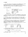
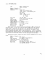
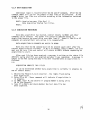
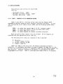
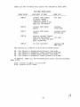
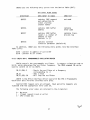
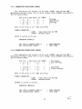
1D$62 uses the following entry points into the Device Table (DVT).
DVT ENTRY POINT USAGE
^
UPON ENTRY TO 1D$62^UPON EXIT
ENTRYPOINT
^
^
contains EXEC request
not used
VT 15
and subfunction to
select starting
channel number
$DVT16^contains EXEC buffer^contains
error code
address^
^
^
contains EXEC buffer ^ contains trans$DVT17
length i.e. number of
mission log
channel to read
(default is 1)
$DVT18
^
contains optional
selection parameter (default=0)
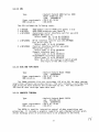
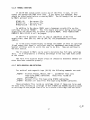
In addition, 1D$62 uses the following entry points into the Interface
Table (IFT):
$1F5 - pointer to address of active DVT
$1F6 - pointer to IFT status
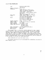
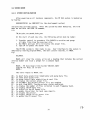
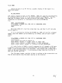
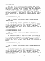
4.4.3 1D$70 SPO-1 PROGRAMMABLE OSCILLATOR DRIVER
1D$70 controls the programmable oscillator. It outputs a function code to
LU 31, which determines the oscillator frequency. The FMGR command CN can be
used to control LU 31 via 1D$70.
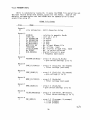
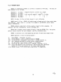
CN,31,25B,-3^- Starts the oscillator at a frequency
corresponding to -3
CN,31^- does a reset
CN,31,25B,-20^- will stop the oscillator
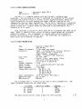
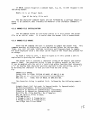
1D$70 is the RTE-A interface driver used with the SPO-1 Programable
Oscillator and a Parallel Interface Card (PIC).
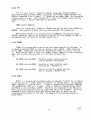
Control EXEC request only are allowed. Read and write requests are
rejected with the appropriate error code set.
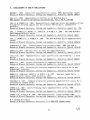
The following error codes are returned in the A register:
0 - No error
1 - Illegal request (read or write)
3 - SPO-1 timed out
27