1
ELECTRICAL WORK
Suggest Minimum Wire Size(AWG:American Wire Gage):
Appliance Amps
AWG Wire Size
10
18
13
16
18
14
25
12
30
10
40
8
NOTE:
The wire size of power supply cord and
interconnected wire and the current of
the fuse or switch are determined by the
maximum current indicated on the
nameplate which located on the side
panel of the unit. Please refer to the
nameplate before selecting the wire size,
fuse or switch.
The controller of the air conditioner
designed with a fuse protection function
under abnormal conditions, the
specifications of the fuse have printed on
the circuit board, such as: T3.15A/250VAC,
T5A/250VAC, etc.
Front Panel
Connect the cable to the indoor unit
NOTE: Before performing any electrical
work, turn off the main power to the system.
1. The inside and outside connecting cable can
be connected without removing the front grille.
2. Lift the indoor unit panel up, remove the
electrical box cover by loosening the screw
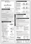
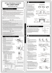
as shown in Fig.22.
3. Ensure the colour of wires of outdoor unit
and the terminal Nos. are the same to the
,
indoor s respectively.
4. Wrap those cables not connected with
terminals with insulation tapes, so that they
will not touch any electrical components.
Secure the cable onto the control board with
the cord clamp.
Electrical box
cover
Terminal block of indoor unit
L1 L2
L
S
N
S
or
To outdoor unit
To outdoor unit
Fig.22
Connect the cable to the outdoor unit
1. Remove the cover control from the unit by
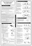
loosening the 3 screws. See Fig.23.
2. Dismount caps on the conduit panel.
3. Temporarily mount the conduit tubes(not included)
on the conduit panel.
4. Properly connect both the power supply and low
voltage lines to the corresponding terminals on
the terminal block.
5. Ground the unit in accordance with local codes.
6. Be sure to size each wire allowing several inches
longer than the required length for wiring.
7. Use lock nuts to secure the conduit tubes.
Outdoor unit
Terminal block
Ove
r13
/5in
.(40
mm
)
G
Connecting
cable
Power supply
cord
Cover control
Fig.23a
10
Conduit panel