1
34
Programming Commands
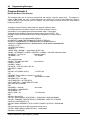
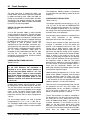
Once in binary dump mode the SR620 will take
data and send it to the controller as fast as it can.
Binary dump mode is terminated when: the count
expires, the front panel reset key is pressed, or
ANY command is received. Because of the last
restriction, the BDMP command should always be
the last command on a command line. The binary
data taken in this mode is NOT buffered. The
SR620 will take a data point, wait until the
controller has read the entire point, take another
point , etc.. Thus the maximum throughput may
be limited by the controller. It is recommended that
some form of direct memory access transfer be
used to maximize the transfer rate.
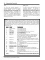
The binary data is return as a 8 byte 2's
complement binary integer. The least significant
byte is always sent first and an EOI is sent with
the most significant byte. To convert this number
to a number with the correct units the following
must be done: 1) Convert the 2's complement
number to signed integer form, and 2) multiply by
a mode dependent scaling factor. The scaling
factors are given below.
Examples of the binary dump mode are given in
the Programming Examples section of the manual.
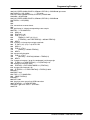
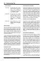
DBEG (?) j
The DBEG command sets the start position of the
internal delay scan. The parameter j is the desired
delay in units of number of gate widths. The
allowable range is between 1 and 50000.
DSEN (?) j
The DSEN command controls the enable status of
the scanning delay. The parameter j = 0 sets the
delay OFF. If j =1 the delay is set to HOLD, that is
, active but fixed in position. If j = 2 the delay is
set to SCAN and will step by 1 step at the end of
each group of samples. Note that the SR620
MUST be in arming mode 6,7, or 8 for the delay
scan to be functional and that an external trigger is
required. (See the SCEN command.)
DSTP (?) x
The DSTP command sets the size of the scanning
delay's step. The range of sizes that may be set is
between 1us and 10ms in a 1,2,5 sequence. The
DSTP? query returns a floating point number with
1 significant digit.
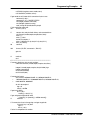
HOLD (?) x
Scan Control Commands
ANMD (?) j
The ANMD command sets the mode of the rear
panel DAC outputs. The parameter j =0 sets
output #0 to produce a voltage proportional to the
measurement mean value, and DAC output #1 to
produce a voltage proportional to the jitter of the
measurement. The parameter j = 1 sets output 0
to be a programmable voltage source and output 1
to be proportional to the jitter. The parameter j = 2
sets output 0 to be proportional to the mean and
output 1 to be a programmable voltage source. If j
= 3 both outputs are programmable sources.
The HOLD command sets the hold time at each
scan point when in scan mode. The hold time
may range between 10ms and 1000s in 10ms
increments. The HOLD? query return the hold
time as a floating point number.
SCAN
The SCAN command clears the current scan and
starts a new scan.
The SCAN command
automatically turns on the automeasure mode.
This command should not be used if one wants to
manually control the acquisition of data during a
scan. One should use the SCLR and STRT
commands instead.
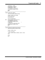
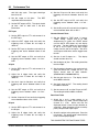
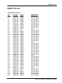
Binary Dump Scale Factors
Time
Width
Rise/fall time
Frequency
Frequency
Period
Period
Phase
Count
Ratio
(2.712673611111111 E-12)/256 ≈ 1.05963812934 E-14
(2.712673611111111 E-12)/256 ≈1.05963812934 E-14
(2.712673611111111 E-12)/256 ≈ 1.05963812934 E-14
(1.0 E 12)/(2.71267361111111 * 2^68) ≈ 1.24900090270331 E-9 (x1000 OFF)
(1.0 E 9)/(2.71267361111111 * 2^68) ≈ 1.24900090270331 E-12 (x1000 ON)
(2.712673611111111 E-12/256 ≈1.05963812934 E-14 (x1000 OFF)
(2.712673611111111 E-15)/256 ≈ 1.05963812934 E-17 (x1000 ON)
360.000/2^32 ≈ 8.3819032 E-8
1/256
1/2^40 ≈ 9.094947017729282 E-13
SR620 Universal Time Interval Counter