1
System Design Concept
•
Nominal output power up to 180W
•
Input current harmonic content will comply with standard IEC 1000-3-2
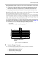
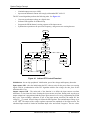
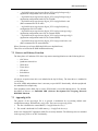
The PFC control algorithm performs the following tasks. See Figure 4-1.
•
Converts sensed output voltage to a digital value
•
Software PID regulator for feedback loop
•
Programs the PWM channel, creating a pattern of the input current
•
Synchronizes operation to the power line frequency, using mean zero crossing detector
Start
Initialise
Wait for mains
zero crossing
Set timer
Wait for output
compare
Select milestone
by pointer
1.milestone
2.milestone
3.milestone
4.milestone
Activate inhibit
Deactivate inhibit
Program PWM
Program PWM
Read Vout
Reset pointer
PID regulator
Program PWM
Increment pointer
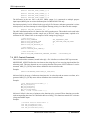
Figure 4-1 Indirect PFC Control Flowchart
Initialization - the on-chip peripherals’ initialization, power line voltage and frequency detection.
Input capture ISR - After the initialization the PFC software waits for the power lines zero crossing
signal, used for synchronization of the PFC algorithm with the line voltage, the time_base for the
milestone table is set.
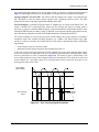
Output compare ISR - The main task of the function is to define the input current waveform
milestones, or time intervals, hence forming the input current waveform. During each step the next
output comparison is programmed and the proper input current level is set by programming the PWM
duty cycle. Upon reaching a milestone of one of the input current waveform, the output DC bus
voltage (Vout) is sensed. Sensed voltage is fed into the PID regulator. The nominal output voltage is set
to 385 VDC. The output of the voltage regulator represents the amplitude of the input current. The
calculated input current is limited to maximum input value and zeroed if negative. The new values
6
Indirect Power Factor Correction