1
VC1 Controller User Manual, Revision 1.9
8
INTERFACING
8.1
Notes on installation
Interfacing
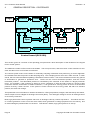
The system relies on the position information from the incremental encoders, and any noise on the encoder
signals can give rise to errors in the absolute position. Care must be taken in installation of the control module
and the encoders to minimise any noise on the encoder signal lines. The encoder interfaces on the PC3/120
board have differential input stages for use with encoders with complementary outputs, providing high rejection
of common-mode noise. In addition, spurious signals on one encoder track produce both an up and a down
count, and thus cancel out. However, in particularly electrically noisy environments it is still possible to get
position counting errors. The system will be set up so that its position is continuously adjusted for any errors by
using a repetitive reference signal to correct them. W ithout such facilities, such errors would otherwise be
accumulated over long periods of continuous operation, unless the system was stopped at regular intervals to
re-initialise the absolute position.
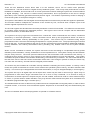
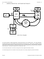
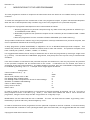
The digital input and output lines are designed to be used with 24 volt logic levels. These lines are optically
isolated from the microprocessor based circuits. This provides protection and allows higher voltage signals to
be used for greater noise immunity.
Copyright © 2006 Pan Controls Limited
Page 79