1
Chapter 3. Nanoprobe MultiSampler Installation
4.
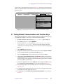
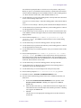
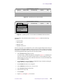
Step through each of the test sequences. The installation of the nms is complete when
all tests function correctly.
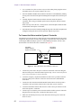
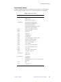
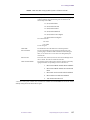
Table 7. NMS Installation Window Buttons and Commands
5.
Button
NMS Command
NMS Action
Insertion (Adjust menu)
F
Insert then remove probe several times.
Rack (Adjust menu)
C
Move sample from the probe to the rack.
Carousel (Adjust menu)
A
Move sample from the probe to the rack.
Insertion (Test menu)
P
Insert probe into the magnet.
Rack (Test menu)
R
Removes sample from the probe and places
sample into the rack.
System (Test menu)
T
Insert then remove probe. Remove sample
from probe and place sample in next rack
position. Retrieve sample and place it in the
probe. Repeat the cycle for all rack
positions.
Establish line shape and resolution for all probes. This is especially important if you
had to rotate the RT shims in “Attaching the Mounting Plate and Elevator” on page
92. The vertical position of the probe is correct if you calculated the shim spacers
correctly as instructed in step 3, page 90.
Using a PC and Zymark System V Software
Connecting and Setting Up the Laptop Computer
This procedure, which is used only during installation or service of the NMS, describes how
to connect the PC laptop computer to the controller and prepare for system power up. Two
different laptop configurations exist— laptops that have an internal serial port (e.g., Toshiba
1800 or 1850) and laptops that have PCMCIA serial cards. Instructions for both
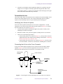
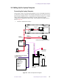
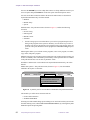
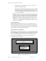
configurations are integrated into this procedure. A block diagram of the NMS system is
shown in Figure 60.
1.
Locate the communication cable(s):
Laptop with internal serial port (2 cables) — one cable has a 15-pin connector at
both ends. The laptop cable has RJ-11/12 phone jack connectors on both ends and
uses the included RJ-11/12 to DB-9 (9-pin) male adaptor.
Laptop with PCMCIA serial card (1 cable) — the cable has a 9-pin female connector
at one end and a 9-pin female connector at the other end. Do not use a null modem
cable or null modem.
2.
Turn off the laptop computer.
3.
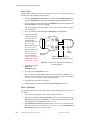
Connect the cables:
Laptop with internal serial port— Connect one end of the RJ-11/12 phone jack cable
to the laptop and the other end to the adaptor (RJ-11/12 to DB-9 male).
Connect the 9-pin connector to the 9-pin connector on the NMS Controller. Connect
the other end of the cable, with the 9-pin connector, to the adaptor connected to the
laptop cable.
102
Sample Management Systems Installation
01-999042-00 D0800