1
22
KUMO Chassis Installation
Where to Place
KUMO
Plan adequate space for cable routing from the back of the chassis. Ensure that SDI video
cable connectors will not be stressed and that cables are not bent or crimped in the
process.
When rackmounting or stacking multiple KUMO chassis, ensure there is adequate
airspace for cooling around the KUMO units. Note the location of cooling vents on all
equipment next to the KUMO and ensure none are obstructed.
Physical
Requirements
When planning equipment locations and mounting methods, take into account the size
of the router chassis:
• Router Dimensions:
1 RU Height – 1.75” (4.45 cm); Depth – 1.5” (3.81 cm); Width – 19” (48.3 cm)
2 RU Height – 3.47” (8.814 cm); Depth – 1.543” (3.92 cm); Width – 19” (48.3 cm)
Power
Requirements
• Input Voltage: 110-220VAC, 50/60Hz to 12 VDC brick converter supply
(fully redundant with optional second brick supply; AJA recommends AJA p/n
103147-00)
• Power Consumption: KUMO 1604 = 9 Watts; KUMO 1616 = 20 Watts;
KUMO 3232 = 26.4 Watts
Caution!
KUMO is designed to take advantage of its chassis to aid in cooling. It is
common and expected for the densely populated 1616 chassis to have a
warm front panel in normal, active operating conditions.
Warning!
Do not open the chassis. There are no user-serviceable parts inside. Opening the
chassis will void the warranty unless performed by an AJA service center or licensed
facility. Remove the brick power supply AC line cord(s) from mains power when
moving the unit.
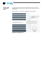
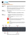
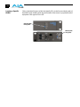
KUMO Connections (3232 shown, other models similar)