1
LAUNCH
X-431 PAD Sensorbox User’s Manual
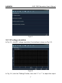
voltage value. Alternatively, user can also click edit box, then use the on-screen
keyboard to input the desired value directly. After selecting or inputting the
desired voltage based on the working characteristics of sensor, click the "Start"
button, then the X-431 PAD will begin to output the simulation voltages. Please
note the red probe is the output terminal of simulation voltage.
Button descriptions:
[Settings]: allows you to adjust the voltage.
[Start]: confirms the current operation.
[Return]: returns to the previous interface.
3.2.2 Fixed frequency simulation
This option enables you to simulate the square wave signal of pulse frequency
of 0.1 ~ 15 kHz, amplitude range of -5V ~ +5 V and duty cycle 10% ~ 90%.
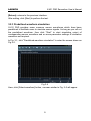
In Fig. 3-1, click "Fixed frequency simulation" to enter a screen similar to Fig.
3-3.
Fig.3-3
Button descriptions:
[Settings]: adjusts the voltage value, duty cycle ratio and frequency of current
square wave signal.
[Start]: confirms the current operation.
8