1
Load Reduction Planning Tool (LRPT) v 2 Technical and User Guidance Document Lahontan Regional Water Quality Control Board (LRWQCB) and Nevada Department of Environmental Protection (NDEP). Lake Tahoe TMDL Pollutant Load Reductions Opportunity Report. March 2008 v.2.0. http://www.waterboards.ca.gov/rwqcb6/water_issues/programs/tmdl/lake_tahoe/docs/presentations/pro_repor
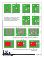
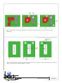
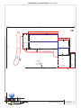
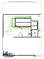
t_v2.pdf Northwest Hydraulic Consultants (nhc), Geosyntec Consultants, and 2NDNATURE. 2009. PLRM Model Development Document. Prepared for Lake Tahoe Basin Storm Water Quality Improvement Committee. South Lake Tahoe. CA. Available for download, as well as full source code and other supporting documents, from www.tiims.org. APPENDIX A. LRPT V2 TUTORIAL PURPOSE Familiarize participants with the usability, functions and outputs of LRPT. The user should have the complete LRPTv2 Technical and User Guidance Document readily available for reference. HYPOTHETICAL SITUATION A single family residential parcel in South Lake Tahoe4 is scheduled for retrofit improvements. The site currently includes minimal TRPA parcel‐based BMPs to reduce sources and generation of the pollutants of concern (sediment and nutrient species). Based on recommended BMP practices and private parcel improvements, one post‐retrofit alternative has been developed that includes a series of Treatment BMPs and source control improvements. The site retrofit alternative will include a number erosion control actions to reduce the sediment generation from the site, the removal of all non‐native vegetation and reduction of fertilizer use. Post‐retrofit, a detailed maintenance plan will be developed and resources allocated to ensure that Treatment BMPs continue to function at their full performance level. You are tasked with using LRPTv2 to estimate the water quality benefits of the retrofit alternative for this site. EXAMPLE RETROFIT SITE Figures 9‐11 present the final maps and data the user will generate for each scenario during LRPT STEPs 1‐4. •
•
•
•
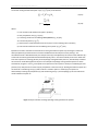
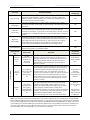
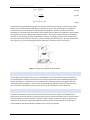
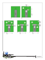
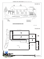
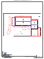
Figure 9A is a schematic of the site pre‐retrofit and figure 9B is a plan view of the site. The parcel is located in MET Grid 847. Figure 10 is the pre‐retrofit site map delineated into patches per LRPT STEP 3 and each patch has been assigned a unique ID. Figure 11 is the pre‐retrofit site map delineated and hydrologic routing contributions (STEP 4) noted for all connected patches. Figure 12 is a post‐retrofit scenario map that includes both patch delineation and hydrologic routing contributions. It is possible to develop and run a number of post‐retrofit scenarios to optimize retrofit design based on the water quality benefit as estimated by LRPT. 4
This parcel is the example parcel in the “How to install best management practices (BMPs) in Lake Tahoe; A guide for building and landscape professionals” (Cobourn et al.) Final November 2010 p. 39 of 52