1
ENG
EVA_2
C
EVA_1
L
EVB_1
EVB
C
CP
F
EVD evolution
EVB_2
twin
EVD evolution
M
twin
S
EEVA
V
S1
S2
S3
S4
S4
S1
S2
S
CP
TB
E
V3
TB
PA TA
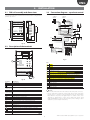
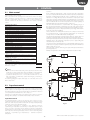
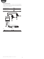
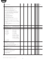
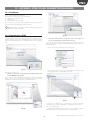
Fig. 5.i
M
T
V1
V2
E
4...20 mA
regulator
H%
Key:
CP
C
L
F
S
TA, TB
Compressor
Condenser
Liquid receiver
Dewatering filter
Liquid indicator
Temperature probe
V
EEVA
EVB
E
PA
Solenoid valve
Electronic expansion valve A
Electronic valve B
Evaporator
Pressure probe driver A
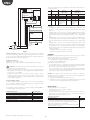
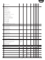
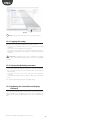
Fig. 5.j
Key:
CP
Compressor
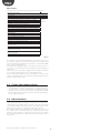
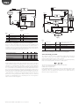
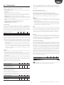
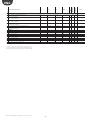
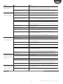
This involves PID control without any protectors (LowSH, LOP, MOP, see the
chapter on Protectors), without any valve unblock procedure. Control is
performed on the hot gas bypass temperature probe value read by input S4,
compared to the set point: “Hot gas bypass temperature set point”. Control is
reverse, as the temperature increases, the valve closes.
C
V1
V3
S
Condenser
Solenoid valve
Non-return valve
Heat exchanger
(reheating)
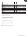
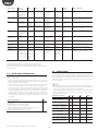
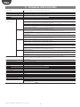
Parameter/Description
CONTROL
Hot gas bypass temperature set point
Def.
Min.
Max.
UOM
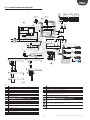
For the wiring, see paragraph 2.11 “General connection diagram”.
10
Transcritical CO2 gas cooler
15
150
5
200
(392)
800
1000
800
°C (°F)
PID: proportional gain
PID: integral time
PID: derivative time
-60
(-76)
0
0
0
s
s
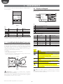
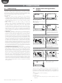
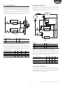
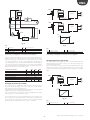
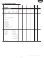
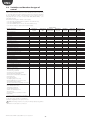
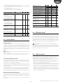
This solution for the use of CO2 in refrigerating systems with a transcritical
cycle involves using a gas cooler, that is a refrigerant/air heat exchanger
resistant to high pressures, in place of the condenser.
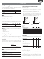
In transcritical operating conditions, for a certain gas cooler outlet temperature,
there is pressure that optimises the efficiency of the system:
For the wiring, see paragraph 2.11 “General connection diagram”.
Tab. 5.o
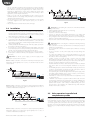
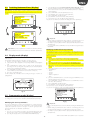
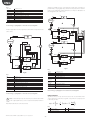
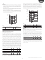
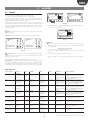
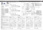
Another application that exploits this control function uses the connection
of two EXV valves together to simulate the effect of a three-way valve, called
“reheating”. To control humidity, valve EVB_2 is opened to let the refrigerant
flow into exchanger S. At the same time, the air that flows through evaporator
E is cooled and the excess humidity removed, yet the temperature is below
the set room temperature. It then flows through exchanger S, which heats it
back to the set point (reheating). In addition, if dehumidification needs to be
increased, with less cooling, valve EVA_2 must open to bypass at least some
of the refrigerant to condenser C. The refrigerant that reaches the evaporator
thus has less cooling capacity. Valves EVA_1 and EVA_2 are also connected
together in complementary mode, controlled by the 4 to 20 mA signal on
input S1, from an external regulator.
“EVD Evolution TWIN” +0300006EN - rel. 2.2 - 19.03.2012
EVA_1, 2
EVB_1, 2
H%
TB
E
V2
Electronic valves connected in
complementary mode
Relative humidity probe
Temperature probe
Evaporator
Thermostatic expansion valve
Set= pressure set point in a gas cooler with transcritical CO2
T= gas cooler outlet temperature
Default value: A=3.3, B= -22.7.
In the simplified diagram shown below control is performed by driver A and
the simplest solution in conceptual terms is shown. The complications in the
systems arise due to the high pressure and the need to optimise efficiency.
Driver B is used for superheat control.
24