1
5,703,678
18
17
probability of a noise pulse appearing over a longer ?ight
algorithm in the microcomputer 270 that allows you to
discriminate between noise pulses and laser return pulses.
What the algorithm does is. during the laser ?ring process.
on the ?rst pulse that fires. it gets a laser pulse. and it places
it in a stack of pulses. For example. the stack may have
locations designated 0 through 9. to enable 10 pulses to be
maintained in the stack. The values of the FLJGHTHME are
saved. corrected for power return. (the microcomputer 270
determines the power level of the return signal and corrects
the ?ight time for power return) and placed in one of the
locations in the stack. Upon receipt of the next pulse. the
microcomputer 270 will then compare the next pulse with
the remaining locations in the stack. Initially. most of the
range. and therefore a quick acquisition on a bright white
target can be achieved. Thus. by depressing the mode switch
126. different modes of operation of the laser range ?nder 10
can be selected. As an example. one mode might be utilized
to ?nd the range to re?ective road signs out to a distance of
1000 yards or more. Alternatively. aiming the laser range
?nder 10 at something like wet black tree bark. might reduce
the maximum range to only 350-400 yards and so a different
operational mode might be selected which would otherwise
locations will be empty. and there will be no match. If no
match is found. the microcomputer 270 puts the pulse in the
stack and carries on. merely placing pulses in the stack. and
then when it gets to the top. it goes back and overwrites the
15
base, so you have a history of N number of pulses in the
stack. Any time a new pulse comes in. it compares the entire
stack for a match. where N=l0. it searches the preceding ten
pulses for a match.
The reason for doing that is. since a high noise ?ring rate
has been deliberately set to get maximum sensitivity. many
noise pulses are going to have shown up. but the noise pulses
will be of random occurrence and the chance of a precision
require a relatively long time to hit the road sign. if ever.
because there would always be a noise pulse in the way. The
mode switch 126 allows the setting of these variables to
maximize the range of the laser range ?nder 10. depending
on the target quality and a visual indication of the target
quality selected may be provided to the operator on the
in-sight. LCD display 32 wherein the ?rst mode would
correspond to the brightest target or most re?ective target.
and the Nth mode would correspond to the least re?ective
target.
While there have been described above. the principles of
the invention in conjunction with speci?c apparatus. it is to
be clearly understood that the foregoing description is made
25
match is very low. Because the tolerance can be set as any
other ?rmware parameter. a default value will be typically
loaded that has been determined empirically. As an example.
only by way of example and not as a limitation on the scope
of the invention.
What is claimed is:
1. A method for determining a range to a target based upon
a ?ight time of a pulse toward said target. said method
a tolerance of a few nanoseconds may be set for a match to
be assumed to be a real target and not a noise pulse. Utilizing
the algorithm. the process continues. trying to lock on the
target until a match is achieved. The match need only be two
30
levels;
?rstly unclamping said second reference signal level to
pulses within the preset tolerance (providing very acceptable
results) or. if higher sensitivity were desired, a match of
three through N may be speci?ed. depending on the reli
ability needed to guarantee a real target and not a noise
35
pulse. In an exemplary operation. the ?rst pulse (pulse 0)
could be the real target. followed by eight noise pulses, and
as long as the ninth pulse is again the real target. the distance
to the target can be accurately determined. The stack can be
increased in size up to whatever memory limit is available
in the system. depending on how far into the noise level the
laser range ?nder 10 must work.
Having found a match. the average of the match values
may then be used to compare all subsequent pulses. rather
than needing to place them in a stack and only pulses that
match up with that initial match average will contribute to
the measurement. If a certain number of pulses elapse before
another matching pulse is received. it may be assumed that
an accidental lock-on to noise has been achieved and the 50
process restarts. By adjusting the various parameters. a trade
oil’ can be made between the time it takes to get a measure
ment to how far into the noise the laser range ?nder 10 must
work. Because the noise rate can set to whatever is desired
by means of the automatic noise threshold section 36. it is 55
possible to optimize the algorithm to provide the optimum
acquisition characteristics against time and against range.
The higher the value of V3. the more noise is coming out
of the receiver. and the more sensitive the laser receive
section 22 is running. The probability of a noise pulse
showing up is proportional to the ?ight time. so given a very
“black” target. the maximum range will be less. but the
maximum ?ight time is also less. so a higher noise rate can
be tolerated. Therefore. running at a higher gain will provide
the best range to a black target. On the other hand. if the 65
target is very re?ective. a high gain is not required. so the
noise rate can be lowered. which then provides the same
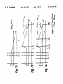
comprising the steps of:
initially establishing ?rst and second reference signal
allow said second reference signal level to approach. at
a ?rst rate. said ?rst reference signal level;
meastn-ing a ?rst reference time T1 from said step of
?rstly unclamping until said ?rst and second reference
signal levels are equal;
re-establishing said ?rst and second reference signal lev
els;
secondly unclamping said second reference signal level
and ramping said second reference signal level. at a
second rate. for a predetermined period of time to
establish a third reference signal level;
allowing said third reference signal level to approach. at
said ?rst rate. to said ?rst reference signal level;
secondly measuring a second reference time T2”, from
said step of secondly unclamping until said ?rst and
third reference signal levels are equal;
again re-establishing said ?rst and second reference signal
levels;
thirdly unclamping said second reference signal level;
again ramping said second reference signal level. at said
second rate. for a period of time related to said ?ight
time of said pulse to said target. to establish a fourth
reference signal level;
again allowing said fourth reference signal level to
approach.‘ at said ?rst rate. said ?rst refm’ence signal
level;
thirdly measuring a third reference time T3,,Jr from said
step of thirdly unclamping until said ?rst and fourth
reference signal levels are equal; and
computing said range to said target as proportional to
(TSd-TIqWI‘LEI-TIMI).
2. The method of claim 1 wherein said steps of initially
establishing. re-establishing and again re-establishing are