1
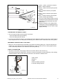
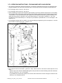
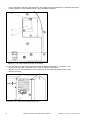
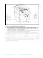
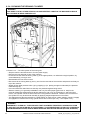
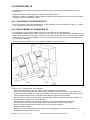
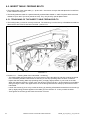
6.12. ELECTRICAL INSTALLATIONS - MAINTENANCE Any repairs of the electrical installations can only be carried out by a person familiar with the technology who has suitable and valid authorisation. To find out faults, always use the electrical documentation which is part of the machine documentation. Make sure that after the repair has been finished all the electrical installations have been put to the original state. It is particularly important to re-connect all the protective cables (if they were disconnected during the repair. Make sure that all the electrical devices are correctly marked in accordance with the operating scheme. Once the repair is finished, check all the safety devices and their settings (limit switches, safety thermostat etc.) Regularly check the state of the machine's earthing. Incorrect earthing may lead to occurrences of static discharges which can cause malfunctioning of the machine and poor ironing quality. Check the state and tightness of the screw terminals of the main switch, contactors and in the case of a machine with electrical heating also of the fuse disconnectors and heaters. Check after the machine has been installed and then after every 1000 operating hours or after six months. 6.13. FREQUENCY INVERTER Frequency inverter (FC) is an electronic device which ensures variable and adjustable speed of the ironing cylinder. FC is installed in the left stand on the switchboard panel situated on the bottom right. The FC parameters are set by the manufacturer and any intervention may only be carried out by authorised personnel. Authorised personnel may (if necessary) load a new parametric set into the FC utilizing a special control panel: o I33_FC_PARAMETER LIST > code: 528333 o Parameter copy unit > code: 528334 The instructions for loading the 528333 parameters from the parameter copy unit into the FC - valid for authorised servicing only: o 1. Switch on the frequency inverter by manually switching the CFI contactor. o 2. Use the Menu button to select the option Main Menu on the display. o 3. Use the arrows to select the parameter set 1 – confirm with OK. o 4. Use the arrows to select the parameter 1-50 – confirm with OK. o 5. Use the arrows to set the PR1-50 to 2 - confirm with OK > it will copy the parameters into the inverter. o 6. Switch the inverter off. If at fault > part of the error message E6 – see chapter 5.9. 6.14. MAIN DRIVE MOTOR The machine is driven by a three-phase induction motor of 180 W rated power. It is supplied with power from the frequency inverter (chapter 6.13.) and it has an integrated worm-gear unit with transmission ratio i = 70 and implemented freewheel clutch with a rated transmitted moment of 50Nm. The motor unit is situated on the driving roller in the left stand of the machine. There is an arrow indicating the correct direction of rotation on the gearbox housing. o Connection to the main switch does not influence the correct direction of rotation. o If power supply is to be connected to the terminal block of the motor, it is necessary to check the correct direction of rotation - in the case that the connection is carried out incorrectly, there is a risk of damage to the gearbox freewheel! The gearbox has a permanent lubrication filling and it is maintenance-free. Check it once a week and focus on: o any potential leakage of the lubrication filling from the gearbox housing, o cleanness of the ventilation (aspirating) grill of the motor positioned in the lower section of the machine, o state of both the silentblocks, which catch the moment reaction of the motor with the gearbox, o If at fault > part of the error message E6 – see chapter 5.9. 545098_G_Pub_date_2_Jan_2014.doc ORIGINAL INSTALLATION AND USER'S MANUAL 67