1
GPIODemo_SRM
Module v0.4
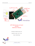
GPIO Demo module
System
Reference Manual
GPIODemo_SRM for Module v0.4
September 10, 2015 - Doc rev 0.4c
Author: Nathaël Pajani
Techno-Innov - DomoTab
http://www.techno-innov.fr
page 1 / 33
GPIODemo_SRM
Module v0.4
Table des matières
1 Introduction
4
2 Licenses
2.1 Documentation . . . . . . . . . . . . . . . . . . . . . . . . . . . . . . . . . . . . . . . . . . . . . . . .
2.2 Hardware . . . . . . . . . . . . . . . . . . . . . . . . . . . . . . . . . . . . . . . . . . . . . . . . . . .
2.3 Software . . . . . . . . . . . . . . . . . . . . . . . . . . . . . . . . . . . . . . . . . . . . . . . . . . . .
4
4
4
4
3 Hardware
3.1 Dimensions . . . . . . . . . .
3.2 Connectors . . . . . . . . . .
3.2.1 P1 Connector . . . . .
3.2.2 P2 Connector . . . . .
3.2.3 P3 Connector . . . . .
3.2.4 P4 Connector . . . . .
3.2.5 P5 Connector . . . . .
3.2.6 P6 and P7 Connectors
3.2.7 P8 Connector . . . . .
3.3 Jumpers . . . . . . . . . . . .
3.3.1 J1 jumper . . . . . . .
3.3.2 J2 jumper . . . . . . .
3.3.3 J3 and J4 jumpers . .
.
.
.
.
.
.
.
.
.
.
.
.
.
.
.
.
.
.
.
.
.
.
.
.
.
.
.
.
.
.
.
.
.
.
.
.
.
.
.
.
.
.
.
.
.
.
.
.
.
.
.
.
.
.
.
.
.
.
.
.
.
.
.
.
.
.
.
.
.
.
.
.
.
.
.
.
.
.
.
.
.
.
.
.
.
.
.
.
.
.
.
.
.
.
.
.
.
.
.
.
.
.
.
.
.
.
.
.
.
.
.
.
.
.
.
.
.
.
.
.
.
.
.
.
.
.
.
.
.
.
.
.
.
.
.
.
.
.
.
.
.
.
.
.
.
.
.
.
.
.
.
.
.
.
.
.
.
.
.
.
.
.
.
.
.
.
.
.
.
.
.
.
.
.
.
.
.
.
.
.
.
.
.
.
.
.
.
.
.
.
.
.
.
.
.
.
.
.
.
.
.
.
.
.
.
.
.
.
.
.
.
.
.
.
.
.
.
.
.
.
.
.
.
.
.
.
.
.
.
.
.
.
.
.
.
.
.
.
.
.
.
.
.
.
.
.
.
.
.
.
.
.
.
.
.
.
.
.
.
.
.
.
.
.
.
.
.
.
.
.
.
.
.
.
.
.
.
.
.
.
.
.
.
.
.
.
.
.
.
.
.
.
.
.
.
.
.
.
.
.
.
.
.
.
.
.
.
.
.
.
.
.
.
.
.
.
.
.
.
.
.
.
.
.
.
.
.
.
.
.
.
.
.
.
.
.
.
.
.
.
.
.
.
.
.
.
.
.
.
.
.
.
.
.
.
.
.
.
.
.
.
.
.
.
.
.
.
.
.
.
.
.
.
.
.
.
.
.
.
.
.
.
.
.
.
.
.
.
.
.
.
.
.
.
.
.
.
.
.
.
.
.
.
.
.
.
.
.
.
.
.
.
.
.
.
.
.
.
.
.
.
.
.
.
.
.
.
.
.
.
.
.
.
.
.
.
.
.
.
.
.
.
.
.
.
.
.
.
.
.
.
.
.
.
.
.
.
.
.
.
.
.
.
.
.
.
.
.
.
.
.
.
.
.
.
.
.
.
.
.
.
.
.
.
.
.
.
.
.
.
.
.
.
.
.
.
.
.
.
.
.
.
.
.
.
.
.
5
5
5
6
7
7
8
8
9
9
10
10
11
11
4 Electronics
4.1 Micro-controller LPC1224 . . . .
4.1.1 Internal RAM . . . . . . .
4.1.2 Internal Flash . . . . . . .
4.1.3 Communication interfaces
4.1.4 GPIO . . . . . . . . . . .
4.1.5 ADC . . . . . . . . . . . .
4.1.6 Reset and ISP mode . . .
4.2 I2C . . . . . . . . . . . . . . . . .
4.2.1 I2C Addresses . . . . . . .
4.2.2 External EEPROM . . . .
4.2.3 Temperature sensor . . .
4.3 User Led and Button . . . . . . .
4.4 USB to UART bridge . . . . . .
.
.
.
.
.
.
.
.
.
.
.
.
.
.
.
.
.
.
.
.
.
.
.
.
.
.
.
.
.
.
.
.
.
.
.
.
.
.
.
.
.
.
.
.
.
.
.
.
.
.
.
.
.
.
.
.
.
.
.
.
.
.
.
.
.
.
.
.
.
.
.
.
.
.
.
.
.
.
.
.
.
.
.
.
.
.
.
.
.
.
.
.
.
.
.
.
.
.
.
.
.
.
.
.
.
.
.
.
.
.
.
.
.
.
.
.
.
.
.
.
.
.
.
.
.
.
.
.
.
.
.
.
.
.
.
.
.
.
.
.
.
.
.
.
.
.
.
.
.
.
.
.
.
.
.
.
.
.
.
.
.
.
.
.
.
.
.
.
.
.
.
.
.
.
.
.
.
.
.
.
.
.
.
.
.
.
.
.
.
.
.
.
.
.
.
.
.
.
.
.
.
.
.
.
.
.
.
.
.
.
.
.
.
.
.
.
.
.
.
.
.
.
.
.
.
.
.
.
.
.
.
.
.
.
.
.
.
.
.
.
.
.
.
.
.
.
.
.
.
.
.
.
.
.
.
.
.
.
.
.
.
.
.
.
.
.
.
.
.
.
.
.
.
.
.
.
.
.
.
.
.
.
.
.
.
.
.
.
.
.
.
.
.
.
.
.
.
.
.
.
.
.
.
.
.
.
.
.
.
.
.
.
.
.
.
.
.
.
.
.
.
.
.
.
.
.
.
.
.
.
.
.
.
.
.
.
.
.
.
.
.
.
.
.
.
.
.
.
.
.
.
.
.
.
.
.
.
.
.
.
.
.
.
.
.
.
.
.
.
.
.
.
.
.
.
.
.
.
.
.
.
.
.
.
.
.
.
.
.
.
.
.
.
.
.
.
.
.
.
.
.
.
.
.
.
.
.
.
.
.
.
.
.
.
.
.
.
.
.
.
.
.
.
.
.
.
.
.
.
.
.
.
.
.
.
.
.
.
.
.
.
.
.
.
.
.
.
.
.
.
.
.
.
.
.
.
.
.
.
.
.
.
.
.
.
.
.
.
.
.
.
.
.
.
.
.
.
.
.
.
.
.
.
.
.
.
.
.
.
.
.
.
.
.
11
12
12
12
13
13
13
14
14
14
14
15
16
16
.
.
.
.
.
.
.
.
17
17
17
17
18
18
18
19
19
.
.
.
.
.
.
.
.
.
.
.
.
.
5 Software
5.1 Sample Source Code . . . . . . . .
5.1.1 Grab the sources . . . . . .
5.1.2 Sample code content . . . .
5.1.3 Sample code entry point . .
5.2 Building the binary . . . . . . . . .
5.2.1 Get a toolchain . . . . . . .
5.2.2 Build command and options
5.2.3 Build process . . . . . . . .
.
.
.
.
.
.
.
.
.
.
.
.
.
.
.
.
.
.
.
.
.
.
.
.
.
.
.
.
.
.
.
.
.
.
.
.
.
.
.
.
.
.
.
.
.
.
.
.
.
.
.
.
.
.
.
.
.
.
.
.
.
.
.
.
.
.
.
.
.
.
.
.
.
.
.
.
.
.
.
.
.
.
.
.
.
.
.
.
.
.
.
.
.
.
.
.
.
.
.
.
.
.
.
.
.
.
.
.
.
.
.
.
.
.
.
.
.
.
.
.
.
.
.
.
.
.
.
.
Techno-Innov - DomoTab
http://www.techno-innov.fr
.
.
.
.
.
.
.
.
.
.
.
.
.
.
.
.
.
.
.
.
.
.
.
.
.
.
.
.
.
.
.
.
.
.
.
.
.
.
.
.
.
.
.
.
.
.
.
.
.
.
.
.
.
.
.
.
.
.
.
.
.
.
.
.
.
.
.
.
.
.
.
.
.
.
.
.
.
.
.
.
.
.
.
.
.
.
.
.
.
.
.
.
.
.
.
.
.
.
.
.
.
.
.
.
.
.
.
.
.
.
.
.
.
.
.
.
.
.
.
.
.
.
.
.
.
.
.
.
.
.
.
.
.
.
.
.
.
.
.
.
.
.
.
.
.
.
.
.
.
.
.
.
.
.
.
.
.
.
.
.
page 2 / 33
GPIODemo_SRM
5.3
Module v0.4
Uploading binary on target . . . . . . . . . . . . . . . . . . . . . . . . . . . . . . . . . . . . . . . . .
5.3.1 Tools . . . . . . . . . . . . . . . . . . . . . . . . . . . . . . . . . . . . . . . . . . . . . . . . .
5.3.2 Connection with target and upload . . . . . . . . . . . . . . . . . . . . . . . . . . . . . . . . .
6 Do It Yourself
6.1 Tools . . . . . . . . . . .
6.2 Materials . . . . . . . .
6.3 Components and options
6.4 PCB preparation . . . .
6.5 Stencil . . . . . . . . . .
6.6 Applying solder paste .
6.7 Pick and place . . . . .
6.8 Hot Plate soldering . . .
6.9 Checks and Fixes . . . .
6.10 Through hole . . . . . .
6.11 Final test . . . . . . . .
6.12 Clean and tidy . . . . .
7 Board revisions history
7.1 v01 . . . . . . . . . . .
7.2 v02 . . . . . . . . . . .
7.3 v03 . . . . . . . . . . .
7.4 v04 . . . . . . . . . . .
.
.
.
.
.
.
.
.
.
.
.
.
.
.
.
.
.
.
.
.
.
.
.
.
.
.
.
.
.
.
.
.
.
.
.
.
.
.
.
.
.
.
.
.
.
.
.
.
.
.
.
.
.
.
.
.
.
.
.
.
.
.
.
.
.
.
.
.
.
.
.
.
.
.
.
.
.
.
.
.
.
.
.
.
.
.
.
.
.
.
.
.
.
.
.
.
.
.
.
.
.
.
.
.
.
.
.
.
.
.
.
.
.
.
.
.
.
.
.
.
.
.
.
.
.
.
.
.
.
.
.
.
.
.
.
.
.
.
.
.
.
.
.
.
.
.
.
.
.
.
.
.
.
.
.
.
.
.
.
.
.
.
.
.
.
.
.
.
.
.
.
.
.
.
.
.
.
.
.
.
.
.
.
.
.
.
.
.
.
.
.
.
.
.
.
.
.
.
.
.
.
.
.
.
.
.
.
.
.
.
.
.
.
.
.
.
.
.
.
.
.
.
.
.
.
.
.
.
.
.
.
.
.
.
.
.
.
.
.
.
.
.
.
.
.
.
.
.
.
.
.
.
.
.
.
.
.
.
.
.
.
.
.
.
.
.
.
.
.
.
.
.
.
.
.
.
.
.
.
.
.
.
.
.
.
.
.
.
.
.
.
.
.
.
.
.
.
.
.
.
.
.
.
.
.
.
.
.
.
.
.
.
.
.
.
.
.
.
.
.
.
.
.
.
.
.
.
.
.
.
.
.
.
.
.
.
.
.
.
.
.
.
.
.
.
.
.
.
.
.
.
.
.
.
.
.
.
.
.
.
.
.
.
.
.
.
.
.
.
.
.
.
.
.
.
.
.
.
.
.
.
.
.
.
.
.
.
.
.
.
.
.
.
.
.
.
.
.
.
.
.
.
.
.
.
.
.
.
.
.
.
.
.
.
.
.
.
.
.
.
.
.
.
.
.
.
.
.
.
.
.
.
.
.
.
.
.
.
.
.
.
.
.
.
.
.
.
.
.
.
.
.
.
.
.
.
.
.
.
.
.
.
.
.
.
.
.
.
.
.
.
.
.
.
.
.
.
.
.
.
.
.
.
.
.
.
.
.
.
.
.
.
.
.
.
.
.
.
.
.
.
.
.
.
19
19
20
.
.
.
.
.
.
.
.
.
.
.
.
20
20
21
21
22
22
23
24
24
24
25
26
26
.
.
.
.
.
.
.
.
.
.
.
.
.
.
.
.
.
.
.
.
.
.
.
.
.
.
.
.
.
.
.
.
.
.
.
.
.
.
.
.
.
.
.
.
.
.
.
.
.
.
.
.
.
.
.
.
.
.
.
.
.
.
.
.
.
.
.
.
.
.
.
.
.
.
.
.
.
.
.
.
.
.
.
.
.
.
.
.
.
.
.
.
.
.
.
.
.
.
.
.
.
.
.
.
.
.
.
.
.
.
.
.
.
.
.
.
.
.
.
.
.
.
.
.
.
.
.
.
.
.
.
.
.
.
.
.
.
.
.
.
.
.
.
.
.
.
.
.
.
.
.
.
.
.
.
.
.
.
.
.
.
.
.
.
.
.
.
.
26
26
26
26
27
8 Annexes
8.1 Schematics . . . . . . . . .
8.2 BOM . . . . . . . . . . . . .
8.2.1 Block version . . . .
8.2.2 Easy order version .
8.3 Document revision History .
8.4 Disclaimer . . . . . . . . . .
.
.
.
.
.
.
.
.
.
.
.
.
.
.
.
.
.
.
.
.
.
.
.
.
.
.
.
.
.
.
.
.
.
.
.
.
.
.
.
.
.
.
.
.
.
.
.
.
.
.
.
.
.
.
.
.
.
.
.
.
.
.
.
.
.
.
.
.
.
.
.
.
.
.
.
.
.
.
.
.
.
.
.
.
.
.
.
.
.
.
.
.
.
.
.
.
.
.
.
.
.
.
.
.
.
.
.
.
.
.
.
.
.
.
.
.
.
.
.
.
.
.
.
.
.
.
.
.
.
.
.
.
.
.
.
.
.
.
.
.
.
.
.
.
.
.
.
.
.
.
.
.
.
.
.
.
.
.
.
.
.
.
.
.
.
.
.
.
.
.
.
.
.
.
.
.
.
.
.
.
.
.
.
.
.
.
.
.
.
.
.
.
.
.
.
.
.
.
.
.
.
.
.
.
.
.
.
.
.
.
.
.
.
.
.
.
.
.
.
.
.
.
.
.
.
.
.
.
.
.
.
.
.
.
.
.
.
.
.
.
.
.
.
.
.
.
27
27
31
31
32
32
33
.
.
.
.
.
.
.
.
Techno-Innov - DomoTab
http://www.techno-innov.fr
page 3 / 33
GPIODemo_SRM
1
Module v0.4
Introduction
You are reading the System Reference Manual for the GPIO Demo module. This manual covers the module
use and design.
The GPIO Demo module is an electronics development and prototyping platform using the LPC1224 microcontroller from NXP 1 .
The LPC1224 micro-controller has a Cortex-M0 ARM core, 32KB of flash memory, 4KB of internal SRAM, and
multiple interfaces.
The module also includes an EEPROM memory and a temperature sensor on the I2C bus, a bi-color user LED (Red
/ Green), a reset button, an ISP mode select / User button, an USB-to-UART bridge (used for programming and
easy communication with the module), 24 GPIO available on 2.54mm pins dispatched for easy use on prototyping
boards and an UEXT connector.
Binaries for the GPIO Demo module can be generated using a gcc ARM toolchain and uploaded using the serial
line (over USB thanks to the integrated USB-to-UART bridge) and our lpcprog tool.
The GPIO Demo module is designed for users interested in embedded ARM micro-controller development using
free, libre and open source softwares only.
Every information about the design is available and all documentations are freely accessible. You can download the
source files for the GPIO Demo module and modify them using KiCad EDA (GPL) according to the license terms
found in the license section. You can create your own GPIO Demo module or a modified version.
In this document the GPIO Demo module will be referred as the module.
2
Licenses
2.1
Documentation
The present document is under Creative Commons CC BY-SA 3.0 License.
It is written in LATEX and the PDF version is generated using pdflatex.
2.2
Hardware
The GPIO Demo module hardware and schematics are under Creative Commons CC BY-SA 3.0 License.
You can produce your own original or modified version of the GPIO Demo module, and use it however you want,
even sell it for profit.
2.3
Software
All the software examples created for the GPIO Demo module are under GPLv3 License.
The lpcprog tool used to program the module is also under GPLv3 License.
1. http://www.nxp.com/products/microcontrollers/cortex_m0_m0/LPC1224FBD48.html
Techno-Innov - DomoTab
http://www.techno-innov.fr
page 4 / 33
GPIODemo_SRM
3
3.1
Module v0.4
Hardware
Dimensions
Fig 1 – USB A board type
Fig 2 – micro USB board type
Fig 3 – Headers and UEXT
connector (2.54mm)
Figures 1, 2 and 3 give the different dimensions and the position of the main elements (connectors, buttons and
user led) of the module.
The only difference between the "USB A" and the "micro USB board types is the USB connector. A part of the
Printed Circuit Board (PCB) is removed on the "USB A" board type to give way for the USB type A male connector.
Note : Not all components are shown on each figure for readability. All components but the USB
connector are the same on both board types.
3.2
Connectors
The module has six 2.54mm pitch headers numbered P1 to P5 and P8, and one USB connector, either P6 or
P7 depending on the board type. Refer to figure 4 for connectors position and to table 1 for a short description.
Detailed description of the signals found on each connector pin follow.
Name
P1
P2
P3
P4
P5
P6
P7
P8
Description
2x5 pins, 2.54mm pitch header.UEXT a connector.
10 pins, 2.54mm pitch header. Provides +5V from USB, ground, and 8 GPIO from port 0.
10 pins, 2.54mm pitch header. Provides 10 GPIO from port 0.
6 pins, 2.54mm pitch header. Provides 6 ADC inputs (can be used as GPIO).
2 pins, 2.54mm pitch header.
USB micro-AB female connector. Available only on micro USB board type.
USB A male connector. Available only on USB A board type.
2 pins, 2.54mm pitch header. Provides access to Rx/Tx on USB to UART bridge.
Table 1 – Module Connectors Description
a. https://en.wikipedia.org/wiki/UEXT
Techno-Innov - DomoTab
http://www.techno-innov.fr
page 5 / 33
GPIODemo_SRM
Module v0.4
Fig 4 – Module Connectors
3.2.1
P1 Connector
Pin #
1
2
3
4
Fig 5 – P1 Connector
5
6
7
8
9
10
Description
+3.3V : +3.3 Volt
GND : Ground
TXD : Transmit Data for UART, connected to LPC RXD on UART 0
(LPC pin 16 : PIO0_1).
RXD : Receive Data for UART, connected to LPC TXD on UART 0
(LPC pin 17 : PIO0_2).
SCL : Clock for I2C bus (LPC pin 25 : PIO0_10).
SDA : Bidirectional Serial Data for I2C bus (LPC pin 26 : PIO0_11).
MISO : Master In Slave Out for SPI bus (LPC pin 31 : PIO0_16).
MOSI : Master Out Slave In for SPI bus (LPC pin 32 : PIO0_17).
SCK : Clock for SPI bus (LPC pin 29 : PIO0_14).
SSEL : Slave Select for SPI bus (LPC pin 30 : PIO0_15).
Table 2 – P1 Connector Pinout
P1 connector is an UEXT 2 connector, as specified by Olimex 3 . The UEXT connector presents power and three
serial buses : UART, I2C and SPI.
P1 connector uses a standard 2.54mm (0.1 inch) pitch header, with 2 rows of 5 pins. It can be either male or female,
and mounted either on top or on bottom of the board. If mounted on top, other components prevent the use of the
common plastic keyed-shroud used for common UEXT connectors. The key would be on the odd pins side, with
2. https://en.wikipedia.org/wiki/UEXT
3. http://www.olimex.com/
Techno-Innov - DomoTab
http://www.techno-innov.fr
page 6 / 33
GPIODemo_SRM
Module v0.4
the module name and Techno-Innov mascot (tibug).
All P1 pins are connected to related pins on the LPC micro-controller. UART Pins are connected to UART 0
and crossed.
Note : The module is designed as an example for module development for the DomoTab platform, thus
the module has the position of a device for the UART pins. This is transparent for the SPI and I2C bus.
3.2.2
P2 Connector
P2 connector is a standard 2.54mm (0.1 inch) pitch header, with 1 row of 10 pins, and can be mounted either on
top or on bottom side of the board.
P2 connector provides access to USB +5V power supply and to 8 GPIO pins from port 0 of the LPC micro-controller.
Pin #
1
2
3
4
5
6
7
8
9
10
Description
+5V : +5 Volt from USB connector
GPIO0_29 : LPC pin 14 : PIO0_29.
GPIO0_0 : LPC pin 15 : PIO0_0.
GPIO0_3 : LPC pin 18 : PIO0_3.
GPIO0_4 : LPC pin 19 : PIO0_4.
GPIO0_5 : LPC pin 20 : PIO0_5.
GPIO0_6 : LPC pin 21 : PIO0_6.
GPIO0_8 : LPC pin 23 : PIO0_8 / RXD1.
GPIO0_9 : LPC pin 24 : PIO0_9 / TXD1.
GND : Ground
Table 3 – P2 Connector Pinout
Fig 6 – P2 Connector
Note : Most P2 pins also provide alternate capture or match input functions for 32-bit timers. Refer
to the LPC1224 documentation from NXP for full documentation of the alternate functions.
Note : When the board is not connected to a power source on the USB port the +5V is not present
on pin 1 of P2 connector.
3.2.3
P3 Connector
P3 connector is a standard 2.54mm (0.1 inch) pitch header, with 1 row of 10 pins, and can be mounted either on
top or on bottom side of the board.
P3 connector provides access to 10 GPIO pins from port 0 of the LPC micro-controller, including Serial Wire Debug
(SWD) pins.
Techno-Innov - DomoTab
http://www.techno-innov.fr
page 7 / 33
GPIODemo_SRM
Module v0.4
Pin #
1
2
3
4
5
6
7
8
9
10
Description
GPIO0_28 :
GPIO0_27 :
GPIO0_26 :
GPIO0_25 :
GPIO0_24 :
GPIO0_23 :
GPIO0_22 :
GPIO0_21 :
GPIO0_20 :
GPIO0_19 :
LPC
LPC
LPC
LPC
LPC
LPC
LPC
LPC
LPC
LPC
pin
pin
pin
pin
pin
pin
pin
pin
pin
pin
13 : PIO0_28.
12 : PIO0_27.
11 : PIO0_26 / SWCLK.
10 : PIO0_25 / SWDIO.
9 : PIO0_24.
8 : PIO0_23.
7 : PIO0_22.
6 : PIO0_21.
5 : PIO0_20.
4 : PIO0_19.
Table 4 – P3 Connector Pinout
Fig 7 – P3 Connector
Note : Most P3 pins also provide alternate capture or match input functions for 32-bit timers and input
or output for comparators. Refer to the LPC1224 documentation from NXP for full documentation of
the alternate functions.
3.2.4
P4 Connector
P4 connector is a standard 2.54mm (0.1 inch) pitch header, with 1 row of 6 pins, and can be mounted either on
top or on bottom side of the board.
P4 connector provides access to 6 GPIO pins from port 0 and 1 of the LPC micro-controller. These pins are inputs
for the A/D converter.
Pin #
1
2
3
4
5
6
Fig 8 – P4 Connector
3.2.5
Description
ADC0 : LPC
ADC1 : LPC
ADC2 : LPC
ADC3 : LPC
ADC4 : LPC
ADC5 : LPC
pin
pin
pin
pin
pin
pin
34
35
36
37
38
39
:
:
:
:
:
:
PIO0_30 / AD0.
PIO0_31 / AD1.
PIO1_0 / AD2.
PIO1_1 / AD3.
PIO1_2 / AD4.
PIO1_3 / AD5.
Table 5 – P4 Connector Pinout
P5 Connector
P5 connector is a standard 2.54mm (0.1 inch) pitch header, with 2 pins, and can be mounted either on top or on
bottom side of the board.
Techno-Innov - DomoTab
http://www.techno-innov.fr
page 8 / 33
GPIODemo_SRM
Module v0.4
P5 connector provides access to the +3.3V regulated power output of the FTDI FT230XS USB to UART bridge
used to power the board when plugged on a USB port. This is also the power received from UEXT connector pin 1.
Pin #
1
2
Fig 9 – P5 Connector
3.2.6
Description
+3.3V
GND
Table 6 – P5 Connector Pinout
P6 and P7 Connectors
P6 and P7 are one-time choice options. Only one of them is present, depending on the board type. Both are
standard USB connectors. P6 is a female micro-AB port, and P7 is a male USB-A port.
Refer to the Universal Serial Bus (USB) 4 page on Wikipedia for pinout and more information on the USB bus and
connectors.
Fig 10 – P6 and P7 Connectors
3.2.7
P8 Connector
P8 connector is a standard 2.54mm (0.1 inch) pitch header, with 2 pins, and must be mounted on top side of the
board.
P8 connector provides access to the Rx and Tx UART signals from the USB-to-UART bridge or the UEXT
connector. Removing J3 and J4 jumpers removes any connection to the LPC1224 micro-controller.
This allows the connection of the USB-to-UART bridge to UART 1 on connector P2, or to any other UART on
another device, provided that you also connect the ground to that other device.
4. http://fr.wikipedia.org/wiki/Universal_Serial_Bus
Techno-Innov - DomoTab
http://www.techno-innov.fr
page 9 / 33
GPIODemo_SRM
Module v0.4
Pin #
1
2
Description
Tx
Rx
Table 7 – P8 Connector Pinout
Fig 11 – P8 Connector
3.3
Jumpers
The module has 4 configuration jumpers, numbered J1 to J4. Jumpers are common to all board types.
Fig 12 – Module Jumpers
Name
J1
J2
J3 and J4
Description
Vref selection.
EEPROM Write protect.
UART0 link to UART from UEXT connector or USB-to-UART bridge.
Table 8 – Module Jumpers Description
3.3.1
J1 jumper
J1 jumper uses a 2.54mm (0.1 inch) pitch header and is used for Vref selection for the LPC internal Analog to
Digital Converter (ADC).
When the jumper is on, Vref is connected to the 3.3V power supply. When the jumper is removed Vref is floating.
Pin 1 of the jumper can be connected to an external reference voltage to provide a stable and known reference
voltage. See section 4.1.5 for more details on Vref and ADC usage.
Techno-Innov - DomoTab
http://www.techno-innov.fr
page 10 / 33
GPIODemo_SRM
3.3.2
Module v0.4
J2 jumper
J2 jumper is used to activate the write protection mechanism of the I2C EEPROM. When the jumper is on the
write protect is off and the EEPROM can be written. When the jumper is removed the EEPROM is in read-only
mode.
3.3.3
J3 and J4 jumpers
J3 and J4 jumpers are used to connect UART0 pins to the FTDI FT230XS USB-to-UART bridge or to the
UEXT connector (P1).
When the jumpers are on the Dev side then the Module is used as a device. This position must be used for binary
upload in ISP mode.
When the jumpers are on the Master side, then the Module is master on the UEXT connector.
Note : Pins Rx and Tx from the USB-to-UART bridge are always connected to the corresponding
UEXT UART pins.
Note : When present, both jumpers must be on the same side of J3 and J4.
4
Electronics
The GPIO Demo module has been created using KiCad 5 EDA software suite for the creation of the schematics
and printed circuit boards.
See page 29 in the annexes for the full schematics. The sources for the schematics are available for download from
the module page 6 on Techno-Innov.fr.
Name
U1
U2
U4
U5
D1
D3
D4
Reset
ISP
Description
LPC1224 ARM Cortex-M0 micro-controller.
I2C EEPROM memory (1kB or 16kB).
I2C TMP101 temperature sensor.
FTDI FT230XS USB to UART bridge.
User led, bicolore (red / green).
Orange led : FTDI Rx activity.
Green led : FTDI Tx activity..
Reset button for LPC1224 (SW2).
ISP mode select button for LPC1224 (SW1).
Table 9 – Module Main Components Description
5. http://www.kicad-pcb.org/display/KICAD/
6. http://www.techno-innov.fr/technique-module-gpio-demo/
Techno-Innov - DomoTab
http://www.techno-innov.fr
page 11 / 33
GPIODemo_SRM
Module v0.4
Fig 13 – Module Main Components
4.1
Micro-controller LPC1224
The module’s micro-controller is a LPC1224 from NXP 7 . The LPC1224 version used on the module is the
LPC1224FBD48/101. All LPC1224 have an ARM Cortex-M0 core running at up to 45 MHz.
The module uses the internal 12 MHz RC Oscillator as main clock. Its 1% accuracy is suitable for most applications.
Note : Refer to the LPC1224 documentation from NXP for full list and documentation of the LPC1224
features. Here are only the descriptions of the features used on the module.
4.1.1
Internal RAM
The LPC1224FBD48/101 has 4kB of internal SRAM mapped in one block at address 0x1000 0000.
4.1.2
Internal Flash
The LPC1224FBD48/101 has 32kB of internal FLASH memory, mapped at address 0x0000 0000. The flash memory programming requires no additional hardware thanks to the In-System Programming (ISP) and In-Application
Programming (IAP) on-chip bootloader software.
See section 4.1.6 (Reset and ISP mode) or sections 5.2 (Code Compilation) and 5.3 (Uploading binary on target)
for more information on internal FLASH memory.
7. http://www.nxp.com/products/microcontrollers/cortex_m0_m0/LPC1224FBD48.html
Techno-Innov - DomoTab
http://www.techno-innov.fr
page 12 / 33
GPIODemo_SRM
4.1.3
Module v0.4
Communication interfaces
The module makes use of the following communication interfaces found on the LPC1224 :
• Two UARTs : UART0 is connected to the UEXT connector and to the USB to UART bridge through J3
and J4 jumpers. UART1 Rx and Tx signals are on P2 connector pins 8 and 9.
UART0 is used for In-System Programming of the LPC1224.
• One I2C bus interface supporting full I2C-bus specification and Fast-mode Plus with a data rate of 1
Mbit/s. I2C is connected to the UEXT connector and to the on-board temperature sensor and EEPROM
memory. See section 4.2 for more information.
• One SSP/SPI controller with FIFO and multi-protocol capabilities. The SPI bus is found on the UEXT
connector. Note that the SPI Slave Select signal is also used by the I2C bus to activate the I2C clock to the
EEPROM memory.
4.1.4
GPIO
The module gives access to 24 GPIO pins (apart from the signals on the UEXT connector (P1) which can be
used as GPIO too), dispatched on P2, P3 and P4 connectors.
Refer to tables 3, 4 and 5 for details of the signals available on these GPIO and to the LPC1224 documentation
from NXP for full list of features for each GPIO.
4.1.5
ADC
Fig 14 – ADC Input Pins and Vref Pin
The six GPIO pins on P4 connector are inputs channels 0 to 5 for the 10-bit ADC of the LPC1224 micro-controller.
Techno-Innov - DomoTab
http://www.techno-innov.fr
page 13 / 33
GPIODemo_SRM
Module v0.4
The internal ADC uses the voltage on the Vref pin as reference voltage for the conversion. Jumper J1 allows you
to use the LPC power supply (approx. 3.3V) as reference voltage (Jumper on). This is the easiest way to use the
ADC, but the measure will not be very accurate as the reference voltage is not precisely known.
If you need more precise conversions you must remove J1 jumper and connect a stable regulated reference voltage
to pin 1 of the jumper J1. You should also add a small capacitor (1 to 100 nF) close to the pin to get a more stable
reference voltage.
4.1.6
Reset and ISP mode
Reseting the LPC1224 without removing the power can be done with the Reset button (SW2).
To enter In-System Programming (ISP) mode after reset you must hold the ISP button (SW1) when you release
the reset button. The LPC1224 bootloader considers a LOW level on the PIO0_12 pin as an external hardware
request to enter ISP mode and start the ISP command handler. The sampling of the GPIO0_12 pin may take up
to 3ms.
Refer to section 5.3 or to the LPC1224 user manual for more information on ISP mode.
If the ISP button is not held when th Reset button is released (and a valid user code is found in Flash memory)
then the execution is transfered to the user program.
4.2
I2C
The module has two elements on the I2C bus : a temperature sensor and an EEPROM memory.
4.2.1
I2C Addresses
I2C Component
1 kB EEPROM
16 kB EEPROM
Temperature sensor
I2C Address R / W
0xA0 / 0xA1
0xA8 / 0xA9
0x94 / 0x95
Table 10 – I2C Addresses
Table 10 shows all the possible I2C Addresses for the components used on the module.
Note : There can be only one EEPROM memory chip at a time on the module. Refer to section 4.2.2
bellow for differentiation between the two possible EEPROM sizes.
4.2.2
External EEPROM
EEPROMs with different sizes fit in the same footprint and can be used on the module, but they use different
protocol depending on the size (one and a half or two memory address words). To allow software to differentiate
those and chose the right protocol, we use different addresses depending on the memory size.
This is transparent from the hardware point of view as the small memory chips ignore the three address configuration
pins found on the EEPROM chips and answer to eight consecutive I2C address couples (R / W) while the bigger
ones take care of "A2" address configuration pin (and only this one in the selected package size).
Techno-Innov - DomoTab
http://www.techno-innov.fr
page 14 / 33
GPIODemo_SRM
Module v0.4
Fig 15 – EEPROM for Module Identification
As shown on figure 15 the hardware sets the A2 address configuration bit to "1", thus only small EEPROMs will
answer to address "0xA0 / 0xA1", while bigger ones answer to address "0xA8 / 0xA9".
In addition to the address differentiation for the EEPROM size access to EEPROM memory requires use of a
particular "EEPROM select" mechanism.
The EEPROM on the DomoTab modules are used to identify the module function, name, version, and possibly
store the task code for the OS to communicate with the module. Many modules can be plugged at the same time
on a single device, and the device needs a mechanism to read only one EEPROM at a given time to identify the
module physical position when the device has many UEXT connectors. This is done using the SPI Slave Select
signal from the UEXT connector. The I2C clock signal (SCL) is not transfered to the EEPROM memory chip when
the SPI SSEL signal is not active (LOW).
This is true even if the module is not plugged on a UEXT connector. Thus before any access to the EEPROM
memory one must activate the SPI SSEL signal (put the GPIO0_15 pins in LOW output state).
Refer to sample code for an example of how this is done in software and for the routines to read and write
EEPROM memory.
4.2.3
Temperature sensor
Fig 16 – Temperature sensor
Techno-Innov - DomoTab
http://www.techno-innov.fr
page 15 / 33
GPIODemo_SRM
Module v0.4
The module has a TMP101 temperature sensor (from Texas Instrument) on the I2C bus (address 0x94 / 0x95).
This temperature sensor has an "alert" function available through a dedicated pin. This pin is routed to a wake-up
capable pin of the LPC1224 micro-controller : GPIO0_7 (pin 22) which allows the temperature sensor to wake the
micro-controller from "Deep-sleep" mode.
Refer to the LPC1224 User Manual from NXP for more information on the "Deep-sleep" mode and to the TMP101
documentation for the temperature alert signal.
4.3
User Led and Button
Fig 17 – User Led
The module has three leds and two buttons. The two leds connected to the USB to UART bridge (D3 and D4)
and the Reset button have dedicated functions and cannot be assigned other functions.
The remaining led (D1) and button (ISP) can be used as the user wishes.
The D1 led is a bi-color red / green led connected to PIO1_4 (pin 40) and PIO1_5 (pin 41). Both can be turned
on at the same time, providing a third color (orange).
Note : The PIO1_4 and PIO1_5 pins are not PWM capable so it’s not possible to create shades
between red and green without using a lot of processing power.
After reset the ISP button can be used by the user to any purpose. It’s state can be read on pin PIO0_12 (pin
27).
4.4
USB to UART bridge
Fig 18 – USB to UART bridge
Techno-Innov - DomoTab
http://www.techno-innov.fr
page 16 / 33
GPIODemo_SRM
Module v0.4
In order to ease the development process and the use of the module we added a USB to UART bridge on-board.
This bridge is made by a FTDI FT230XS chip. It provides a 3.3V regulated voltage for the module and is well
supported on most operating systems so there is usually no configuration required to use it as a serial line on the
host development system, removing the need of any additional power source or of specific hardware to program the
LPC1224 micro-controller and communicate with the module.
The FTDI chip controls two "activity" leds for Rx (D3, the orange one) and Tx (D4, green one) data over the
serial link.
Removing jumpers J3 and J4 disconnects the USB to UART bridge from the LPC1224 micro-controller which
allows connection of the bridge to other UARTs on other devices using Rx and Tx signals on connector P8.
5
Software
The LPC micro-controller family uses ARM cores, which make them very easy to use. Apart from a few wrappers,
all the code can be written in C and compiled using gcc.
ARM, NXP and other vendors provide sample code, but published under many different licences. The code we
provide for the GPIO Demo module is published under the well known GPLv3 licence.
5.1
5.1.1
Sample Source Code
Grab the sources
An example application code can be downloaded from our git repository 8 using the following clone command :
user@host:˜/sw$ git clone http://gitclone.techno-innov.fr/modules
5.1.2
Sample code content
This code provides the micro-controller definitions (Cortex-M0 specific definitions, registers, interrupts ...) and
the routines required to start the micro-controller (bootstrap, vector table, power state, flash, clocks).
At the time of writing it also provides a basic set of library functions and the drivers for the interfaces found
on the module. The list of supported features and interfaces is updated as the development goes on, so read the
README file for the full list of supported features and interfaces.
The code has been split in five parts : core/ , drivers/ , extdrv/ , apps/ and lib/ (with the associated
directories under include/ for the headers) :
• core : Contains all the required parts and system initialisations. Many functions in there are defined as
weak aliases of dummy functions, so the code compiles even if no drivers are used. When these functions are
redefined in the driver code they override the weak definition.
• lib : Contains the implemented parts of the small C library for our code. The micro-controller does not run
a full Linux system, so the gnu libc must not be used, and even a µClibc is much more than what’s required.
Most of the code in these files come from the kernel implementations of libc parts.
8. http://git.techno-innov.fr/?p=modules;a=summary
Techno-Innov - DomoTab
http://www.techno-innov.fr
page 17 / 33
GPIODemo_SRM
Module v0.4
• drivers : Contains the drivers for the different interfaces found on the module.
• extdrv : Provides drivers for external components, either on the module (EEPROM, status led, tmp101
temperature sensor), or to be purshased separately and connected to the module.
The number of external parts supported will grow with time. Note that it may not be possible to use all of
them at the same time.
• apps : Provides sample applications for the different modules made by Techno-Innov which demonstrate
either LPC1224 interfaces or external drivers, which can be used as base for your own developments.
Most modules will have their own directory under apps/ . The GPIO Demo module uses the base/ subdirectory, which is common with the GPIO Demo module. Creating a new app is as easy as creating a new
sub-directory under apps/base (with no spaces or special caracters in the name), copying the Makefile
from one of the other apps in your new app directory, and creating your own C source file(s) (maybe starting
with a copy of an existing example).
If you created a new module, you should consider creating a new "module" directory under apps/ with it’s
own sub-directories for specific apps.
5.1.3
Sample code entry point
The main loop is in main.c in function main() , as with any C program, though main() is called by the
bootstrap code ( Reset_Handler() in core/bootstrap.c ) and could have any name.
The calls to the system initialisation routines have been put together in the system_init() function.
SELECTED_FREQ must be set to one of the FREQ_SEL_**MHz defined in include/core/system.h :
• FREQ_SEL_12MHz
• FREQ_SEL_24MHz
• FREQ_SEL_36MHz
• FREQ_SEL_48MHz
• FREQ_SEL_60MHz
Note : The frequency can go up to 60MHz despite what is said in the documentation, but the microcontroller needs much more power at higher frequencies.
Note : system.h provides two sleep functions ( msleep() and usleep() ). These will activate the
systick with a 1ms tick if it has not been done yet.
Note : usleep() ma
The pins used by your application should be configured using either the set_pins() function and pio_config
structures (see common_pins[] in most examples) or the config_gpio() function for each used pin.
5.2
5.2.1
Building the binary
Get a toolchain
Build has been tested using gcc, and only gcc, in the version provided by the emdebian project 9 , but any ARM
gcc toolchain should do.
In order to get the emdebian ARM gcc cross-toolchain you should add this repository to your apt sources :
deb http://www.emdebian.org/debian/ unstable main .
Then update and install package gcc-4.7-arm-linux-gnueabi .
It may be required that you create a symlink in /usr/bin for the arm gcc using one of these :
9. http://www.emdebian.org/
Techno-Innov - DomoTab
http://www.techno-innov.fr
page 18 / 33
GPIODemo_SRM
Module v0.4
root@host:˜# cd /usr/bin && ln -s arm-linux-gnueabi-gcc-4.7 arm-linux-gnueabi-gcc
or
root@host:˜# update-alternatives -install /usr/bin/arm-linux-gnueabi-gcc
arm-linux-gnueabi-gcc /usr/bin/arm-linux-gnueabi-gcc-4.7 60
There’s no need for the related libc package here, the libc does not fit in our micro-controller memory. Instead
have a look at the content of the lib/ directory, and add stuff there.
Alternatively you can download pre-compiled gcc toolchains (many different projects provide their own), or build
your own one using crosstool-ng 10 or similar projects. For more information on what is a (cross-)toolchain, have a
look at this information page on elinux.org 11 .
5.2.2
Build command and options
Once done with the toolchain installation (or if you already have one) you should build using the provided
Makefile by running the simple " make " command from any of the apps/base/ sub-directory.
You can also build all apps by running " make " from repository root directory or " make base/my_app " to compile
" my_app " from the apps/base/ sub-directory only. ( base may be replaced by any other module name). NoteYou
may want to change the CROSS_COMPILE variable from the main Makefile (in the repository root directory)
and set it to the prefix of your toolchain.
5.2.3
Build process
The specific information about the target (LPC1224 micro-controller) memory (Flash and RAM) used by the
linker is in the lpc_link_lpc1224.ld linker script.
The vector table is defined in the core/bootstrap.c file, but the checksum of the first seven entries in the
vector table is left unmodified. This checksum must be computed and placed in the eighth vector entry as the
bootloader needs to find a valid checksum in the eighth entry to consider the user code as valid and transfer
execution to the reset handler (first vector table entry).
This is done by the lpcprog tool before sending the binary to the target.
5.3
5.3.1
Uploading binary on target
Tools
To flash the binary (the one with .bin) to the LPC Flash you can use our lpctools package, packaged for Debian
as of 2014-09-10 and available in jessie or newer versions, or available in the lpctools git repository 12 .
Lpctools is released under GPLv3 licence.
Clone the repository using :
10. http://crosstool-ng.org/
11. http://elinux.org/Toolchains
12. http://git.techno-innov.fr/lpctools
Techno-Innov - DomoTab
http://www.techno-innov.fr
page 19 / 33
GPIODemo_SRM
Module v0.4
user@host:˜/sw$ git clone http://gitclone.techno-innov.fr/lpctools
Then build ( make ) the tools.
Note : Other tools may be used but have not been tested. No tools were found to be open source when
we looked for tools to upload the binaries to the micro-controller. You must check that the tool you
chose to use can take care of the checksum computation.
5.3.2
Connection with target and upload
Usual command line to upload a binary to the micro-controller :
user@host:˜/sw$ lpcprog -d /dev/ttyUSB0 -c flash mod_gpio.bin
Part ID 0x3640c02b found on line 18
Flash now all blank.
Checksum check OK
Flash size : 32768, trying to flash 8 blocks of 1024 bytes : 8192
Writing started, 8 blocks of 1024 bytes ...
user@host:˜/sw$
If you want to get information on the connected device use the id command of lpcprog :
user@host:˜/sw$ lpcprog -d /dev/ttyUSB0 -c id
Part ID 0x3640c02b found on line 18
Part ID is 0x3640c02b
UID: 0x1228f5f5 - 0x4b324307 - 0x08333834 - 0x4d7b2c1a
Boot code version is 1.6
user@host:˜/sw$
Note : The part information definition for each supported micro-controller is in the lpctools package.
See lpctools readme and lpcprog or lpcisp help (-h option) or manpages for more information.
6
Do It Yourself
This section is dedicated to those who bought the kit to build the module themselves, or to those who bought
the components on their own, or created a modified version of the module and need some help to put the parts
together and get an operational module.
6.1
Tools
The module assembly requires few tools, but you’ll need them :
• Precision tweezer (though any tweezer will do).
• Hot plate (or hot skillet, or equivalent stuff).
• Soldering iron, for the through hole parts (connectors and jumpers).
• Dremel or coping saw for those who want the USB A board type.
• A magnifier may also come in handy, especially for the small temperature sensor (U4) and the multifunction
gate (U3).
Techno-Innov - DomoTab
http://www.techno-innov.fr
page 20 / 33
GPIODemo_SRM
Module v0.4
• A multimeter for the checks, though not required, may be helpful.
For the hot plate, almost any kind of hot plate should do, but it should have a plane surface, and provide a
temperature of 250°C or more. Reflow oven, or any oven able to provide 230*C or more should be OK.
We will concentrate our explanations on the use of a hot plate, but you can find information about other approaches
to solder SMD components in this sparkfun tutorial 13 , which is where I learnt about the hot plate soldering method
we now use to manufacture our products.
Note : There are other solutions to solder the board, including hand soldering tricks. Use your favorite
search engine on the Internet if you are interested in alternate solutions.
6.2
Materials
All the material required is included in the soldering kit, but if you did not chose to buy one from us, here is
what you need :
• Solder paste.
• Desoldering wire. You may not need it if you are very careful with the solder paste application and get the
right amount of solder paste, but I often need some.
• Solder (wire) for the through hole parts.
For the solder paste, we tested only one and are happy with it. When you chose solder paste, take care of the
melting temperature. The lower the temperature, the less risk to damage the components. But be careful of those
with melting temperature below 200°C, they certainly contain lead.
6.3
Components and options
Refer to the Bill Of Material (BOM) page 31 to check that you have all the component. There are two presentations
of the BOM with the same content, one with identical references put together, and one ordered by functional blocks.
Our kits contain all the components, including both P6 and P7 connectors (USB-A male and micro-USB AB
female) though you need only one of them.
Of course, alternate parts can be used for many of the references from our BOM. If you chose an alternate
component, check for the footprint and the pinout.
All the pin headers are not necessary either, and you can chose to solder wires or components directly to the Printed
Circuit Board (PCB) instead.
If you chose not to populate the EEPROM write protect jumper (J2), remember that you will need a strap to
program the EEPROM once.
And of course you can chose to solder only some of the components. For example if you do not need the temperature
sensor (U4) for your application you can leave it apart, including the decoupling capacitor (C4) and pull-up resistor
(R7) used for it. The "functional blocks" version of the BOM is split in separate functional parts to ease the
identification of such groups of components.
Note : If you bought one of our kits, do not remove the parts from the paper they are taped on. Many
parts look similar and have no clue to differentiate one from another.
13. https://www.sparkfun.com/tutorials/59
Techno-Innov - DomoTab
http://www.techno-innov.fr
page 21 / 33
GPIODemo_SRM
6.4
Module v0.4
PCB preparation
If you want to solder the micro USB board type (micro-AB USB connector - P6) you have nothing particular to
do for this step. Only make sure the PCB is clean and dry.
Fig 19 – PCB Part to remove for USB A board type
For those who want to solder the USB A board type (USB A connector - P7), you must remove the PCB part
holding the micro-USB connector.
To remove this part the best tool is a dremel, though any coping saw will do perfectly. Be very careful with either
of these tools, and use a bench vice or a clamp to hold the board firmly while you work on it, but be careful not to
damage the coper tracks (use a small wooden plank or a folded paper to protect the PCB).
6.5
Stencil
Fig 20 – Place stencil and apply solder paste
To ease the solder paste application on the Printed Circuit Board (PCB) we provide a SMD stencil. This stencil
has been laser cut in a Rhodoid sheet (usually used for cooking). It’s transparency makes it easy to position the
stencil over the PCB.
• First of all, fasten the PCB to the worktop, either with adhesive or with blu-tack (used to fix posters to walls).
I prefer the blu-tack solution as it will be possible to use it to maintain the stencil in the right position.
Techno-Innov - DomoTab
http://www.techno-innov.fr
page 22 / 33
GPIODemo_SRM
Module v0.4
• Tear off the removable part of the stencil, it makes a little squeegee you’ll need to apply the solder paste (it’s
the corner with three small bonds to the rest of the stencil).
• Position the stencil on top of the PCB. The position is OK when the holes fit on the solder pads of the PCB.
• Then use the solution you chose to maintain the PCB for the stencil, so it will not move while you apply the
solder paste. The stencil must not bend over the PCB.
Note : If you want to cut your own stencils, keep in mind that the laser will melt the plastic and holes
will be bigger than planned. Reduce the size of the holes by 10 to 40% to get the right hole size.
The holes sizes depend on the thickness of the Rhodoid sheet (100 µm to 150 µm), and must be adjusted
to get the right amount of solder paste in the hole when you remove the stencil.
6.6
Applying solder paste
Solder paste application is made easy using the SMD stencil. Once the stencil is settled on the PCB, get some
solder paste on it. No need to use too much, you’ll be able to add more later if you did not get enough in the first
place.
Use the removable part of the stencil to spread the solder paste over the PCB (make sure there is some solder in
every hole) and remove any excess of solder by scrapping the stencil with the squeegee.
Note : The holes size is proportional to the Rhodoid thickness, so there must not be bumps of solder
above the stencil surface.
You can now remove the stencil. Start raising one corner while you hold the rest in place, so the solder stays in
the right position. Check on the PCB that the solder stayed on the PCB and not in the stencil holes. If some
solder stayed in the holes, don’t care, so long as there’s enough on the PCB. If there’s only one or two spots where
the solder did not stay, do not start again from scratch, rather add some solder using the point of a needle, or
remember these spots and we will see later how you can add solder to a pin of a SMD part easily.
Fig 21 – Solder paste after removing the stencil
Note : Do not panic if the solder chose to stay on the stencil, it is re-usable. Wipe the solder from the
PCB with a paper towel and start again.
Techno-Innov - DomoTab
http://www.techno-innov.fr
page 23 / 33
GPIODemo_SRM
6.7
Module v0.4
Pick and place
You now need to populate the board with the SMD parts (and only these ones). This is an iterative task, starting
with one reference from the BOM, getting the parts out of the reel segment (remove the thin plastic cover which
holds them in place), and place the parts on the PCB. Make sure you do not place them in the wrong place by
referring to the placement sheet included in the Kit. Each pin of the part must lay on some solder.
Be careful of the orientation of the big parts which have a mark for the first pin, and for the Leds for which the
mark is on the bottom of the Led !
The placement of the components does not have to be perfect as the liquid solder will gather under each pin and
align the part. If the solder makes an uniform layer when you put the part down on it it’s no problem either, for
the same reason.
Note : The marks for U2, U3 and U4 are hard to see, use oblique light if you do not have a magnifier
at hand.
Note : There is no real order for the parts placement, but I prefer starting with the small SMD resistors
and capacitors as the solder paste is sticky at the beginning of the process and thus they will stay in
the right spot if the board moves (alone, of course ...).
6.8
Hot Plate soldering
Once you are done with the placement of all the SMD components you can move to the effective soldering process.
This part is the easiest. Place the board on the hot plate (the parts should stay in place while you move the board,
but be careful anyway) and before turning the power on, give a try at removing the board without difficulty. I use
the tweezers and pick the board by the holes of the headers.
Turn the power on. Be very careful as the plate is now gonna be very hot !
You will notice easily the start of the reflow process as the solder will turn shiny when getting liquid. Depending
on the power of the device the process may take between one to four or five minutes. When every solder spot has
melted, turn the hot plate power off and remove the board. Be very careful with this step and do not drop the
board or the components will move before the solder had time to cool down.
6.9
Checks and Fixes
Note : For this part, you will need to have an easy access to the Schematics, to prevent destroying the
board while trying to remove a connection between two pins which seems to be done by an excess of
solder while both pins are connected to the ground plane ... (sounds like I did it ?)
The first check is a visual one. You must make sure that no two consecutive pins got soldered together by an
excess of solder paste. These are easy to see (Figure 22), and also easy to remove.
Techno-Innov - DomoTab
http://www.techno-innov.fr
page 24 / 33
GPIODemo_SRM
Module v0.4
Fig 22 – Short circuits where there was to much solder paste
Fig 23 – Using desoldering wire
• For those with only a little amount of solder, clean the iron tip with a paper towel (careful, it’s very hot) and
apply it between the two pins and push slightly when the solder has melted. If it does not work, move to the
second solution.
• For the other, use the desoldering wire (you’ve got some in the soldering kit, it’s the copper braid). Put the
end of the desoldering wire on top of the solder bump (do not hold it to close to the end, it will become hot
too) and put the iron (cleaned) on top of it and push a little bit so the braid is well in contact with the bump
of solder to be removed. Refer to Figure 23
Note : Use a clean part of the desoldering wire, or it will not soak up the solder. When some length of
the wire is stained with solder, cut it away with pliers.
The second check is making sure every pin got enough solder. Start by looking at those you noticed when you
removed the stencil and were lacking solder paste. A visual inspection may be enough here too. Use of a magnifier
may help. The other way to check is with a multimeter if you have one. Use the connectivity check mode and make
sure there is contact between the top of the pin and what lays at the other end of the coper track.
When you find a pin with a lack of solder the fix is easy. Do not use solder wire, it will bring too much solder
at once, and you’ll get short circuits. Use solder paste. Take a small amount of solder paste with the point of the
tweezers and put it down where you want it. Then use the solder iron to melt it.
6.10
Through hole
Once you are done with checking the result of the hot plate soldering you can start the last soldering step, the
easy one, and solder all the through hole connectors (headers and jumpers).
Use the plastic jumper to hold the headers to avoid burning your fingers. And of course, use the solder wire, not
the solder paste.
Techno-Innov - DomoTab
http://www.techno-innov.fr
page 25 / 33
GPIODemo_SRM
Module v0.4
Do not forget to fill the used USB connector holes, they are here to secure the connector to the PCB, preventing
any constraint on the pins when you plug the cable in.
I usually add some solder to the push buttons. This is no required, but makes them more strong.
6.11
Final test
For the final test, plug the board on your computer and look at the bi-color led, it should show two very small
glow, one red and one green.
You can also look at your system logs, and get some messages about a new USB serial device.
6.12
Clean and tidy
You think you’re done ?
Sounds like you’re right. But your workplace will look better with some cleanup :) Give it a thought at least :)
7
7.1
Board revisions history
v01
This board revision has not been sold.
It was a first test with no temperature sensor, no USB-to-UART bridge, and no possibility to use it on a breadboard
for prototyping.
7.2
v02
This board revision has not been sold.
Very close to the v03 board, but with smaller buttons (almost no pressure feedback, no "click") and an error on
the I2C EEPROM size differentiation mechanism (using A0 pin for the bigger sizes, which is not available on the
selected package)
7.3
v03
First sold version, mainly for the Ulule crowdfunding campaign. (20 boards produced)
No errors known, but the user must disable UART0 (software configuration) in the LPC micro-controller to use the
board as a simple USB-to-UART adapter. The UART comming from the USB connector is available on the UEXT
connector (P1).
Techno-Innov - DomoTab
http://www.techno-innov.fr
page 26 / 33
GPIODemo_SRM
7.4
Module v0.4
v04
Actual version sold as of writting of this documentation.
Added P8 connector to enabled easy access to the UART comming from the USB-to-UART bridge.
Modified J3 and J4 function.
Added ground plane on the top layer.
Added optional capacitor on Vref pin (use 10nF 0402).
8
Annexes
8.1
Schematics
The board schematics and PCB layout have been created using KiCad 14 EDA software suite. You can download
the sources on the module page 15 on Techno-Innov.fr.
(See on next pages)
14. http://www.kicad-pcb.org/display/KICAD/
15. http://www.techno-innov.fr/technique-module-gpio-demo/
Techno-Innov - DomoTab
http://www.techno-innov.fr
page 27 / 33
C
B
R1
100k
Programmation
Reset and
ISP mode selection
SW2
0603
P7
GND
ID
D+
D-
+V
1
2
3
4
1
2
3
4
5
MUSB
1
1
R12
1.5k
0603
DGND
2
0603
USBDM
USBDP
Ferrite Bead
FB1
LPC_RX
LPC_TX
M1
DGND
10uF
GPIO0_9
GPIO0_8
GPIO0_6
GPIO0_5
GPIO0_4
GPIO0_3
100nF
DGND
100nF
C9
11
9
8
Reset
USBDM
USBDP
U5
SPI_SCLK
SPI_CS
SPI_MISO
SPI_MOSI
C6
0603
GPIO0_0
Mire
+5V
2
1
33
32
31
30
29
28
27
26
25
24
23
22
21
20
19
18
17
16
15
DGND
10uF
C1
2
DGND
FT230XS
Sleep
TxDEN
RxLED
TxLED
TxD
RxD
RTS
CTS
SSOP-16
LQFP48
XTALOUT
XTALIN
PIO0_18/SWCLK
PIO0_17/MOSI
PIO0_16/MISO
PIO0_15/SSEL
PIO0_14/SCK
RESET/PIO0_13
16
15
14
7
1
4
2
6
+3,3V
0.1uF
C3
PIO0_12/CLKOUT
PIO0_11/SDA
PIO0_10/SCL
PIO0_9/TXD1
PIO0_8/RXD1
PIO0_7/CTS0
PIO0_6/RIO
PIO0_5/DCD0
PIO0_4/DSR0
PIO0_3/DTR0
PIO0_2/TXD0
PIO0_1/RXD0
PIO0_0/RTS0
U1
0402
0.1uF
C2
Découplage
+3,3V
2mm
2
VREF
45
46
42
41
40
39
38
37
36
35
34
14
13
12
11
10
9
8
7
6
5
4
Rx / Tx Switch
2mm JP3X1
JP3X1
1
D3
LED 0603
1
D4
LED 0603
2
2
270
270
0603
1
3
5
7
9
P1
2
4
6
8
10
UART RX
I2C SDA
SPI_MOSI
SPI_CS
3
2
1
A2
Red
K
D1
Green
SOT-23
A1
UART_TX
UART RX
0603
R4
270
R3
270
0603
DGND
DGND
GPIO0_9
GPIO0_8
GPIO0_6
GPIO0_5
GPIO0_4
GPIO0_3
GPIO0_0
1
2
3
4
5
6
7
8
9
10
(+5V from USB)
4
4
3
2
1
7
8
U2
4
SDA
SCL
ID
5
6
I2C SCL
GPIO0_19
GPIO0_20
GPIO0_21
GPIO0_22
GPIO0_23
GPIO0_24
GPIO0_25
GPIO0_26
GPIO0_27
GPIO0_28
+3,3V
DGND
1
2
3
4
5
6
7
8
9
10
3
2
1
+3,3V
TMP101
V+
AD0
SOT23-6
SDA
ALERT
GND
SCL
U4
2
1
1
2
3
4
5
6
DGND
I2C SCL
SPI_CS
4
5
6
DGND
5
I2C SDA
Rev: 0.4
Id: 1/1
100nF
C4
+3,3V
Temperature sensor
DGND
+3,3V
AD5
AD4
AD3
AD2
AD1
VSS
U3
AD0
DGND
SOT363
In1
In2
In0
VDD
74XX1G58
I2C SDA
Out
GPIO for development
EEPROM
GND
A2
A1
A0
WP
VCC
5
Module identification at startup
TEMP_ALERT
DGND
+3,3V
Licence : Creative Commons - CC - By - SA - NC
Techno-Innov
File: Module_GPIO_Demo.sch
Sheet: /
Title: Module GPIO Demo
Size: A4
Date: 15 oct 2013
KiCad E.D.A.
Bicolor LED
+5V
DGND
GPIO0_29
Note : UART Tx and Rx are from host,
they must be crossed
Note : UEXT female connector mounted on bottom
male connector mounted on top.
LPC_RX
LPC_TX
J4
AD5
AD4
AD3
AD2
AD1
AD0
GPIO0_29
GPIO0_28
GPIO0_27
GPIO0_26
GPIO0_25
GPIO0_24
GPIO0_23
GPIO0_22
GPIO0_21
GPIO0_20
GPIO0_19
+3,3V
R10 0603
R11
+3,3V
UEXT Connector
3
UART_TX
I2C SCL
SPI_MISO
SPI_SCLK
LPC1224
LPC1224FBD48/101
RTCXOUT
RTCXIN
PIO1_6
PIO1_5/AD7
PIO1_4/AD6
PIO1_3/AD5/WAKEUP
PIO1_2/SWDIO/AD4
PIO1_1/R/AD3
PIO1_0/R/AD2
PIO0_31/AD1
PIO0_30/AD0
PIO0_29/ROSC
PIO0_28
PIO0_27
SWCLK/PIO0_26
SWDIO/PIO0_25
PIO0_24
PIO0_23
PIO0_22
PIO0_21
PIO0_20
PIO0_19
DGND
0.1uF
C7
Rx and Tx leds
Choose two different colors
J3
DGND
+3,3V
J1
0
TEMP_ALERT
C5
Mire
+3,3V
M2
0
MIRE_RONDE
0603
I2C SCL
I2C SDA
USB_5V
USB Type A male
P6
microUSB type AB
female
DGND
SW1
Reset
ISP
R2
100k
+3,3V
0603
M0
R13
1.5k
0603
0402
Mire
0402
0402
UEXT
MIRE_RONDE
0402
47
VDD_IO
VSS_IO
48
44
VDD_3V3
VSS
1
3
VREF_CMP
2
43
1
2.54mm
3
J2
0
1
A
USB
2
R5
100k
2
1
0603
2mm
P2
GPIO0_x
MIRE_RONDE
5
GND
10
3V3Out
12
3
VCC
VCCIO
GND
13
3
P3
GPIO0_x
2
P8
0402
1
USB-UART
P5
MSOP_8
1.5k
0603 R7
P4
ADC
Alim
C
B
A
GPIODemo_SRM
8.2
8.2.1
Module v0.4
BOM
Block version
Part Description
Micro-controller
LPC1224
Decoupling capacitors 100nF
Filter capacitor 10µF
Pull-Up resistors 100k Ohms
I2C Pull-Up resistors 1,5k Ohms
Bi-color Led resistors 100 Ohms
SMD Led Red / Green
SMD switchs
UEXT connector
UEXT female connector 2x5
Temperature sensor
Decoupling capacitors 100nF
Pull-Up resistors 100k Ohms
I2C temperature sensor TMP101
USB Bridge
Led resistors 270 Ohms
Decoupling capacitors 100nF
Filter capacitor 10µF
SMD chip bead
Rx Led - Orange
Tx Led - Green
FT230XS USB to UART
Micro-USB type A-B female
USB Type A male
Male headers 1x3
Jumpers 2mm black
UART Connector (2 pins)
Identification
Pull-Up resistors 100k Ohms
Multi-function 74LVC1G58DW
EEPROM 1Ko 8x256 400kHz
GPIO Connectors
Male headers GPIO (30 pins)
Jumpers 2.54mm black
Vendor
Vendor ref
Farnell
ref
1
2
1
2
2
2
1
2
NXP
Multicomp
TDK
Multicomp
Multicomp
Multicomp
Kingbright
Multicomp
LPC1224FBD48/101
MCCA000050
C1608X5R0J106M
MC0063W06031%100K
MC0063W06031%1K5
MC0063W06031%100R
KM-23ESGW
DTSM-32S-B
1862465
1758896
2112705
9330402
9330607
9330364
1142614
9471898
2,54mm
1
Multicomp
2214S-10SG-85
1593490
C4
R7
U4
0402
0603
SOT-23
1
2
1
Multicomp
Multicomp
TI
MCCA000050
1758896
MC0063W06031%100K 9330402
TMP101NA/250G4
1207304
R10, R11
C6, C9
C5
FB1
D3
D4
U5
P6
P7
J3, J4
0603
0402
0603
0603
0603
0603
16SSOP
SMD
SMD
2mm
P8
2,54mm
2
2
1
1
1
1
1
1
1
2
2
1
Multicomp
Multicomp
TDK
TDK
Vishay
Vishay
FTDI
Molex
Multicomp
Fisher
Harwin
Fischer
MC0063W06031%270R
MCCA000050
C1608X5R0J106M
MMZ1608R601A
VLMO1300-GS08
VLMG1300-GS08
FT230XS
47590-0001
MC32605
SLY1.085.50G
M22-1900005
SL1.025.36Z
R5
U3
U2
0603
SOT-363
MSOP-8
1
1
1
Multicomp
Diodes Inc.
Microchip
MC0063W06031%100K 9330402
74LVC1G58DW-7
1893838
24AA08-I/MS
1331278
P2, P3, P4,
P5, J1
2,54mm
1
Fischer
SL1.025.36Z
9729038
1
Harwin
M7686-05
3218480
Ref
Module
Nb
U1
C2, C3
C1
R1, R2
R12, R13
R3, R4
D1
SW1, SW2
LQFP48
0402
0603
0603
0603
0603
SOT-23
P1
9330917
1758896
2112705
1669700
2251473
2251461
2081321
1568022
1696546
9729135
510932
9729038
Table 11 – BOM by functional block
Note : Components used on Board may change for functionnally equivalent references without prior
notice
Techno-Innov - DomoTab
http://www.techno-innov.fr
page 31 / 33
GPIODemo_SRM
8.2.2
Module v0.4
Easy order version
Vendor
Vendor ref
1
1
1
1
1
1
NXP
TI
FTDI
Microchip
Diodes Inc.
TDK
LPC1224FBD48/101
TMP101NA/250G4
FT230XS
24AA08-I/MS
74LVC1G58DW-7
MMZ1608R601A
Farnell
ref
1862465
1207304
2081321
1331278
1893838
1669700
0402
5
Multicomp
MCCA000050
1758896
0603
2
TDK
C1608X5R0J106M
2112705
0603
4
Multicomp
MC0063W06031%100K 9330402
0603
0603
0603
SOT-23
0603
0603
2
2
2
1
1
1
2
1
1
1
2
2
Multicomp
Multicomp
Multicomp
Kingbright
Vishay
Vishay
Multicomp
Molex
Multicomp
Multicomp
Fisher
Harwin
MC0063W06031%1K5
MC0063W06031%100R
MC0063W06031%270R
KM-23ESGW
VLMO1300-GS08
VLMG1300-GS08
DTSM-32S-B
47590-0001
MC32605
2214S-10SG-85
SLY1.085.50G
M22-1900005
9330607
9330364
9330917
1142614
2251473
2251461
9471898
1568022
1696546
1593490
9729135
510932
1
Fischer
SL1.025.36Z
9729038
1
Harwin
M7686-05
3218480
Part Description
Ref
Module
LPC1224
I2C temperature sensor TMP101
FT230XS USB to UART
EEPROM 1Ko 8x256 400kHz
Multi-function 74LVC1G58DW
SMD chip bead
U1
U4
U5
U2
U3
FB1
C2,
C3,
C4, C6, C9
C1, C5
R1,
R2,
R5, R7
R12, R13
R3, R4
R10, R11
D1
D3
D4
SW1, SW2
P6
P7
P1
J3, J4
LQFP48
SOT-23
16SSOP
MSOP-8
SOT-363
0603
Decoupling capacitors 100nF
Filter capacitor 10µF
Pull-Up resistors 100k Ohms
I2C Pull-Up resistors 1,5k Ohms
Bi-color Led resistors 100 Ohms
Led resistors 270 Ohms
SMD Led Red / Green
Rx Led - Orange
Tx Led - Green
SMD switchs
Micro-USB type A-B female
USB Type A male
UEXT female connector 2x5
Male headers 1x3
Jumpers 2mm black
Male headers GPIO + UART (32
pins)
Jumpers 2.54mm black
P2, P3, P4,
P5, P8, J1
SMD
SMD
2,54mm
2mm
2,54mm
Nb
Table 12 – BOM by reference
Note : Components used on Board may change for functionnally equivalent references without prior
notice
8.3
Document revision History
Version
Date
Author
Information
0.3a
September 12, 2013
Nathaël Pajani
Initial revision
0.3b
November 06, 2013
Nathaël Pajani
Fixed P2 connector description for pins 8 and 9
0.4a
January 17, 2015
Nathaël Pajani
Updated for board version (v04)
0.4b
April 04, 2015
Nathaël Pajani
Fixed BOM and License information
0.4c
September 10, 2015
Nathaël Pajani
Changes according to code organisation modifications
Techno-Innov - DomoTab
http://www.techno-innov.fr
page 32 / 33
GPIODemo_SRM
8.4
Module v0.4
Disclaimer
The GPIO Demo module is provided "as is" without warranty of any kind, either expressed or implied, including,
but not limited to, the implied warranties of merchantability and fitness for a particular purpose. The entire risk
as to the quality and performance of the GPIO Demo module is with you. Should the GPIO Demo module prove
defective, you assume the cost of all necessary servicing, repair or correction.
Techno-Innov - DomoTab
http://www.techno-innov.fr
page 33 / 33