1
DPhy Decoder
MIPI 1.5Gb/s Protocol Decoder
Hardware DataSheet
&
User Manual
March 2013 - Rev 1.0
1
MIPI DPhy Decoder
1.0 General:
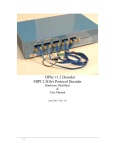
The MIPI DPhy Decoder (DPhyDkd) is the hardware probe that supports protocol decode
on a host Windows PC.
The DPhyDkd supports:
• sophisticated real-time triggering
• real-time record filtering
• status monitoring
• activity statistics
• status LED indicators
• active probes, solder-down, for minimal loading of the device under test.
The control and decode software that is provided with DPhyDkd (DPhyDecoderCtl)
interfaces to the hardware and provides the following features:
• Configuration control
• Disassembly of the captured information in a logic analyzer- like format.
• Reassembly and display of any video information captured
• Storage of captured video frame(s) to a file(s).
Refer to the DPhyDecoderCtl document for a detailed treatment of all the
software features.
DPhyDkd support up to 4 data lanes and 1 clock lane. Data rate operation up to 1.5 Gb/s
per lane is supported. Connection to the DUT is via 5 active solder-down probes
(supplied), one per lane. Power for the DPhyDkd comes from an external desktop
universal power supply. It also features a “Trigger” output on an SMA connector. It can
drive into a 50 ohm termination.
Configuration and control and PC acquisition of the captured data from the DPhyDkd is
via a USB 2.0 connection to the PC-based software application DPhyDecoderCtl. Refer
to the DPhyDecoderCtl manual for the details of operating this software.
2.0 Requirements:
• The DPhyDkd must be connected to a PC via USB 2.0.
• The PC must be running the DPhyDecoderCtl.
• The PC must be running Microsoft Windows XP or Win7-32 / 64 bit.
• The MIPI DPhy signals being monitored must be nearly within specification.
This becomes more important as the link bitrate increases.
Updated versions of the instrument firmware can be found on our MIPI website:
www.movingpixel.com/MIPI.html.
2
3.0 Connections and Indicators
3.1 USB
The USB connection between the unit and the PC is made via the rear panel. The
connector is labeled “USB”. It accepts the “B” end of a standard USB 2.0 cable.
3.2 Power
This is covered in the next section “Usage”.
3.3 Front Panel Indicator LEDs
There are 8 front-panel indicators. Except as noted, they are “sticky” in that if an event
occurs, the LED will light for a fixed period of time so that a human observer can see it
happen.
From left to right they are and indicate as follows:
Idle
Green. There is no traffic at the present time
HSTraffic
Green. There is High Speed traffic present.
LP Traffic
Green. There is Low Power traffic present.
BTA
Green. A Bus Turn Around cycle is in progress
ULPS
Green. Bus is in Ultra Low Power State.
Trigger
Green. The trigger conditions specified via the GUI have been met.
Errors
Red, not sticky (the associated indicator in the GUI is sticky). CRC and/or
Checksum errors have been detected. The reason this indicator is not
sticky is so that a user can get a real-time feel for the error rate and
feedback if the user is making an adjustment that may affect the error rate.
Spare – Yellow, this is reserved for future use. Currently it comes on at power up and
stays on.
3
3.5 Analog Monitor
On the rear panel of the unit is a port called “Analog Monitor”. This port provides 3
signals derived from each lane inside the probe head. For each lane we provide a singleended LP+ and LP- signal and a copy of the differential signal. The analog monitor port
is intended to drive 50 ohm loads.
The signals are output on an AMP Mictor connector. The unit is provided with a short
cable that mates with the DPhyDkd connector. A user can mate the other end to a
compatible connector, AMP 767054-1, for example.
TMPC has available a breakout board that mates with this cable and provides SMA
connectors for more convenient connection to other equipment. Nexus also sells a Mictor
to square pin breakout system, although the performance of this is probably not adequate
for most DPhyDkd uses.
The pinout for the cable is shown below:
Pin
5
7
9
11
13
15
17
19
21
23
25
27
29
31
33
35
Signal
ground (no SMA)
Lane 0 diff+
Lane 0 diff –
ground (no SMA)
Lane 1 diff+
Lane 1 diff –
ground (no SMA)
Lane 2 diff+
Lane 2 diff –
ground (no SMA)
Lane 3 diff+
Lane 3 diff –
ground (no SMA)
Clock Lane 1 diff+
Clock Lane 1 diff –
ground (no SMA)
Pin
6
8
10
12
14
16
18
14
14
24
14
14
30
32
34
36
Signal
ground (no SMA)
Lane 0 LP +
Lane 0 LP ground (no SMA)
Lane 1 LP +
Lane 1 LP ground (no SMA)
Lane 2 LP +
Lane 2 LP ground (no SMA)
Lane 3 LP +
Lane 3 LP ground (no SMA)
Clock Lane LP +
Clock Lane LP ground (no SMA)
The signals out of the Analog Monitor port are copies of the original signal. Copies are
not exact replicas. The differential signal is typically offset -225 mV from actual with a
gain of 1.1 (110 percent), So if the signal was 200mV peak-peak offset from 0 by 200
mV, the Analog Monitor version could be 220mV peak to peak offset from ground by
-25mV. The differential bandwidth is -3dB at roughly 750 MHz (1500 Mbps).
The performance of the LP signals is as follows: roughly 60 MHz -3dB bandwidth, gain
= 1.0, offset = 0 volts.
4
3.6 Probe heads
5 active, solder-down probe heads have been provided: one for the clock lane and one
each for up to 4 data lanes. Lanes are labeled at the Preprocessor end of the cable.
For the highest electrical performance, the probes are designed to be soldered directly to
the D-PHY signal lines. Center to center spacing is 0.050”. If a particular application
can stand some stub, we recommend a small whisker of wire be soldered between the
probe end and the circuit under test. This will give the system some mechanical
flexibility and will help prevent damage to either the probe tip ends or the circuit under
test.
Unused probe heads should be wrapped up in an antistatic container such as a nickel bag.
If a user expects to not use particular lanes long-term, the probe head and cable can be
unplugged and removed from inside the Preprocessor. Removal will keep the probe head
out of the user’s way and lessen the likelihood of damage (but remember where you put
it; they are easy to lose and quite expensive to replace!).
Probe polarity is identified in the following illustration. Probe + should connect to
D-PHY lane Dp , with probe – connecting to D-PHY Dn. If the input resistors to the
probe become damaged as a result of soldering/de-soldering, etc., they may be replaced
with 1.33 K 1% 0603 resistors. All normal soldering and ESD precautions must be
observed.
Probe head tip resistors are user-replaceable. 10 spare resistors are provided for each
probe head. Users are cautioned that probe tip resistor soldering replacement requires a
fair bit of skill in order to avoid damage to the probe head circuit board.
CONNECTOR
on back
+
HEATSHRINK
(color varies, clear shown)
When soldering the probe directly to traces or pads or vias, care must be taken to prevent
mechanical stress to the probe head else circuit damage may result.
5
The colors on the end of the probes are meaningless. They are provided to help with
probe logistics. When shipped, Data Lane one is Red, Data Lane two is Green, Clock is
Clear, Data Lane three is Blue, and Data Lane 4 is White (following the resistor color
code). The probes are all interchangeable, including the clock.
For usage information, see section 4 below.
6
4.0 Usage
Connect data cables from the DPhyDkd to the TLA, the USB cable to the PC, and the
probe heads to the DUT. Make sure the black ground wire is attached to the DUT
ground.
We have found that the best way to connect the solder-down probes to the DUT is to
solder short (~7mm) “whisker” wires to each of the probe tips then down to the DUT.
Tie the probe head to the DUT with some electrical tape to stabilize the setup and strailrelieve the whisker wires.
If short whisker wires cannot work for a particular setup, the user can extend the length to
the probe head by soldering a 100-200 ohm resistor to the DUT then extending the other
end to the probe head. This wire can be up to ~40mm before significant signal
degradation occurs. Note that this additional resistance will cause some degradation of
the DPhy signal amplitude. In critical applications, the probe tip resistors value should be
reduced by the amount of the additional external resistance.
Connect the external 5 volt power supply to DPhyDkd via the connector on the rear panel
marked “5 Vdc”.
CAUTION: This product is often used in the vicinity of a P331/P332/P338 probe. The
P331/P332/P338 probe uses an external power supply similar to that used for this probe,
particularly the power output connectors are IDENTICAL! If the DPhyDkd is powered
by the P331/P332/P338 supply (+24Vdc, not +5Vdc), it will be completely destroyed
instantly. Repairs required because of mis-application of power is NOT covered by
the product warranty. We ship all P331/P332/P338 probe power supplies with an orange
tag attached to the power output cord to help warn the user of this situation.
Note that there is a LED visible through a hole next to the power connector. This LED
will light with a green color when power is applied to the unit.
Upon power-up, the left-most two leds (“Idle” and “HS Traffic”) will blink back and
forth a few times to indicate that the internal boot process is complete.
This system is intended to be operated in a lab environment where proper grounding of
all equipment and surfaces is implemented. The system monitors very small signals
across a very wide frequency range and is easily upset by large EM fields and static
discharges.
7
4.1 Clock delay line setting
The DPhyDkd was designed to operate with systems that may not be within spec,
particularly with respect to the clock-to-data timing relationship. We have provided an
adjustment available through the GUI so that a user can optimize the timing. As the user
operates closer to the maximum clock rate limit for the DPhyDkd (the setting becomes
more sensitive with number of lanes), this setting gets very critical, working over a 220pS
range typically at 1.5Gbps. A clue that the timing needs adjustment is that the DPhyDkd
has no errors at lower frequencies. If we see errors at the highest bit rates, we try
changing this setting over a +/- 200pS range. The GUI has a button that automates the
search for the best possible setting of this delay line.
8
5.0 Electrical specification for the DPhyDkd
Characteristic
Maximum data rate
Maximum clock rate
Input Impedance, active probes
Trigger Out, impedance
Specification
1.5 Gb/s
750 MHz
2.0k to ground in
parallel with less than
1pF, each side of the
Differential input
~50 ohms
Trigger Out, amplitude
~3.3V open circuit
1.65V into 50 ohms
Probe Head tip resistors
1.33k, 1%
Storage
Clock delay range
External Power Supply
Operating Environment
Notes
per lane
This will slightly reduce the
LP voltage high signal
depending on the output
impedance of the source
Logic low is ground.
0603 package style, lead-free
16MBytes/lane
~9 nS
5 Vdc, 30 watts max
20-30 degrees C
Less than 15,000’
elevation
No condensing humidity
Weight
~1170 grams
Weight, power supply and cord ~475 grams
Overall Dimensions
345mm x 195mm x
80mm
Universal, supplied
Lab environment
No strong, stray fields
No static discharges
approximate, without supply
approximate
Approximate, without supply
Note that this product is RoHS compliant, even though it is currently exempt from RoHS
requirements.
9
For more information contact:
The Moving Pixel Company
4905 SW Griffith Drive
Suite 106
Beaverton, Oregon 97005
www.movingpixel.com
information@movingpixel.com
+1.503.626.9663 phone PST
10