1
Accessory 8K2
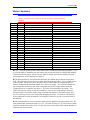
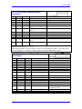
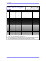
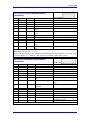
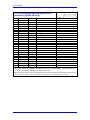
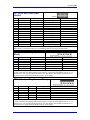
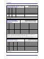
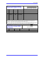
Motor I-Variables
WARNING:
Always disconnect motors from the driven load when running with flags
disabled.
I-Var.
Ix00
Ix01
Ix02
Ix03
Ix04
Ix08
Ix09
Ix25
Ix29
Ix61
Ix62
Ix66
Ix69
Ix70
Ix71
Ix72
Ix76
Ix77
Ix78
Ix79
Ix82
Ix83
Ix84
Value
Description
1
1
default
default
default
96
96
$C2xxxx
0
0
0
See Note
See Note
2
4096
85
0
0
0
0
See Note
See Note
$FFF000
Motor x Activate
Commutate Enable
Command Output Address
Position Loop Address
Velocity Loop Address
Positive Loop Scale Factor
Positive Velocity Scale Factor
Limit/Home flag/Amp flag Address
Output/First Phase Offset
Current Loop Integral Gain
Current Loop Prop. Gain (Forward)
PWM Scale Factor
Output Command Limit
Number of Commutation Cycles
Encoder counts per Rev.
Commutation Phase Angle
Current Loop Proportional Gain (Backpath)
Induction Motor Mag Cur
Induction Motor Slip Gain
Output/Second Phase Offset
Current Loop Feedback Address
Commutation Position Address
Current-Loop Feedback Mask Word
Notes
Enable motor calculations
Enable commutate calculations
See PMAC2 Software Reference
See Software Reference
See Software Reference
See Software Reference
See Software Reference
Defeat limit flags n
Will Be Set During Current Loop Tuning
Will Be Set During Current Loop Tuning
Voltage Output Scaling o
Max Current Level Limit p
Number of Pole Pairs q
qr
Set for IPB value.
Will Be Set During Current Loop Tuning
Will be Set After Current Loop Tuning
Will be Set After Current Loop Tuning
See PMAC2 Software Reference s
See PMAC2 Software Reference t
Bit mask for 12 bit A-D converter
n The ‘2’ will defeat limit switches when added to the Limit/Home Flag/Amp Flag address. This
is put in the table to remind the user that motors will not run if the flags are enabled with nothing
connected to the flag inputs. When reset, the PMAC2 default values are acceptable for typical
axis assignments, except that flags are enabled.
o The Ix66 parameter is used to limit the maximum drive PWM allowed into the motor phase
coils. This value must be non-zero to perform the motor setup procedures. Ix66 is scaled in units
to I900 or I906. When Ix66 is set to the same value as I900 or I906, the voltage applied to a
motor will approach the maximum that the servo driver can supply. The Ix66 value should take
into account the ratio between the motor’s maximum line-to-line voltage and the actual bus
voltage that the servo amplifier may deliver. The value of Ix66 should be set to I900 + 10%
(2401) when the bus voltage on the servo amplifier is close to the voltage rating of the motor.
When the motor’s maximum voltage rating is less than the amplifier’s maximum output, Ix66
must be scaled to prevent excess current from damaging the motor. If a motor is used that has a
current rating that exceeds the amplifier, Ix66 might be reduced to prevent overcurrent faults in
the amplifier.
p The Ix69 parameter is used to scale how much current is applied to the motor phase coils. The
Ix69 parameter has a maximum value of 32,767. The ratio of Ix69 to 32,767 will scale how much
current is provided to the motor coils. Use the peak current of both the motor and the amplifier to
determine the Ix69 parameter.
12
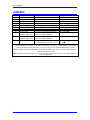
I-Variable Assignments