1
Assembly and Operating Manual
Linear actuator LM
7 Handling
7.1 End position sets
The stop screw LMAS-... must only be used for short stroke lengths, low stroke speeds
and low kinetic energy levels!
Shock absorber stops (LMST-...) should be used as standard.
The following components are available for limiting of stroke length, damping and detection of
end positions:
LMAS-... (Stop screw)
LMST-... (Shock absorber stop)
LMNS-... (Proximity switch - complete)
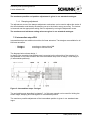
The diagram below shows the installation of LMST-... and LMNS-... in accordance with installation variant 1 (internal). For installation in accordance with installation variant 2 (external), the
switching pin and damper adjustment mechanism are interchanged with LMST-... and LMNS-...
(not in the case of LM 25)
Damping Adjustment Dimension Z
LMST-...
LMD-...
LMNS-...
Switch Stud
Clamp Screw
Stroke
Figure 1: linear actuator end position sets
7.1.1
Adjustment of linear actuator stroke length
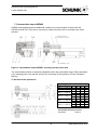
The stroke length of the linear actuator can be adjusted, after the clamping screw has been
loosened, by adjusting the shock absorber stop and proximity switch jointly by means of a fine
thread (not in the case of LM 25). Subsequent adjustment of the end position interrogation is not
necessary. Once the required stroke length has been set, the clamping mechanism must be
tightened again.
Max. permissible screw tightening torque for grade 8.8:
LM 25
1.5Nm
LM 50
1.5Nm
LM 100
3.0Nm
LM 200
5.9Nm
LM 300
5.9Nm
8
Date printed 23.02.2010