1
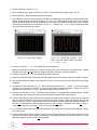
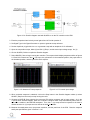
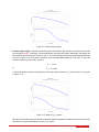
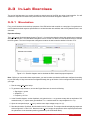
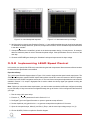
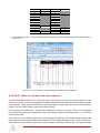
Figure 3.3.2: Ideal lead speed response.
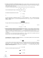
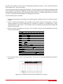
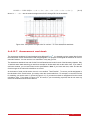
Figure 3.3.3: Ideal lead motor input voltage.
6. Varify that the time-domain specifications in Section 3.1.1 are satisfied and that the motor is not being saturated.
To calculate the steady-state error, peak-time, and percent overshoot, use the simulated response data stored
in the data v variable.
7. If the specifications are not satisfied, go back in the lead compensator design. You may have to, for example,
add more maximum phase in order to increase the phase margin. If the specifications are met, move on to the
next step.
8. Generate a MATLAB figure showing the Simulated Lead speed response and its input voltage.
3.3.2 Implementing LEAD Speed Control
In this section, the speed of the IP02 cart is controlled using the lead compensator. Measurements will then be taken
to ensure that the specifications are satisfied.
Experiment Setup
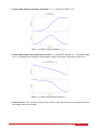
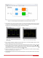
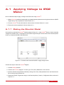
The q ip02 speed Simulink diagram shown in Figure 3.3.4 is used to implement the speed control experiments. The
IP02 Speed subsystem contains QUARC blocks that interface with the DC motor and sensors of the IP02 system,
as discussed in the QUARC Integration Lab Section A. The Lead Control subsystem implements the lead controller
detailed in Section 3.1.2, except a high-pass filter is used to obtain the velocity signal (as opposed to taking the
direct derivative).
Note: Before you can conduct these experiments, you need to make sure that the lab files are configured according
to your IP02 setup. If they have not been configured already, then go to Section 3.4.2 to configure the lab files before
you begin.
1. Run the setup ip02 speed script.
2. Enter the Kc , a, and T parameters found in Section 3.1.2.2.
3. Set Signal Type in the Signal Generator to square to generate a step reference.
4. Set the Amplitude (m/s) gain block to 0.1 to generate a step with an amplitude of 0.2 meters.
5. Open the cart speed scope, Meas.(0) and Sim.(1) Resp., and the motor input voltage scope, Vm (V).
6. Click on QUARC | Build to compile the Simulink diagram.
IP02 Workbook - Student Version
v 1.0