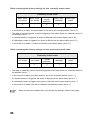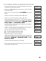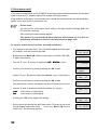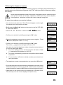
1
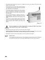
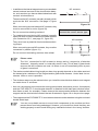
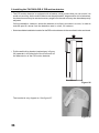
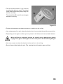
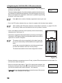
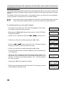
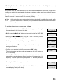
• To mark the drill hole for this screw (or to tighten the screw), the casing of the alarm base station must be opened. All the larger casings of the ‘FAZ’ system comprise a front shell and a rear shell which are connected by 2 catches on the right side. A catching system on the left side of the casing, which is comprised of catches on the front shell and catch slots on the rear shell, serves to close the half shells. Using a flat screwdriver, carefully push the 2 catches approx. 1 millimetre inwards until the half shells separate (see arrow in the figure on the right). First press one catch inwards and pull the casing approx. 2-3 millimetres apart at this location. Then press the other catch inwards; the casing now opens. Figure 12 Do not straighten any of the components or additional PCBs in the alarm base station just so that it ‘looks better’. • Depending on the type of wall, drill a hole and insert a dowel. Mark the position for the drill hole, using a ballpoint pen refill, for example. Then remove the alarm base station from the wall, drill the hole (6mm) and insert a dowel. • Afterwards, hang the alarm base station on the 2 upper screws again. 24 Please note: Do not tighten the third screw yet, as the cabling must be carried out first. Otherwise the cables cannot be fed into the alarm base station from the lower opening.