1
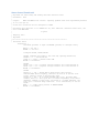
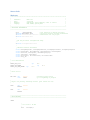
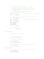
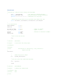
movf
andlw
movwf
movlb
CCPTMRS0,W,A
b'11100100'
; both C2TSEL and C1TSEL set to 0
CCPTMRS0,BANKED
0x00
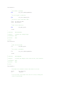
;
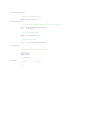
; Enable PWM Mode on CCP1 and CCP2
;
;
b7-6='00' - unimplmented
;
b5-4='00' - LOW order bits of PWM Duty Cycle
;
b3-0='1100' - Enable PWM Mode
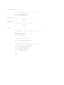
movlw 0x0C
movwf CCP1CON,A
movwf CCP2CON,A
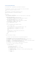
;
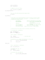
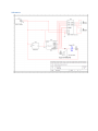
; Configure pins 7-3 on PortC for use as output (motor control)
;
; We are using:
;
;
RC7 - EN (enable bit on motor control board)
;
RC6 - IN1_M1 - Motor 1 input 1
;
RC5 - IN2_M1 - Motor 1 input 2
;
RC4 - IN1_M2 - Motor 2 input 1
;
RC3 - IN2_M2 - Motor 2 input 2
;
movf TRISC,W,A
andlw b'00000111'; clear TRISC bits<7:3> to set pins as output
movwf TRISC,A
;
; Start with the motor off
;
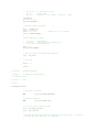
movlw
MOTOR_SET_OFF
movwf PORTC,A
return
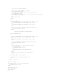
;
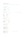
; Function:
;
; Purpose:
;
;
; Parameters:
;
;
; Returns:
;
; Notes:
;
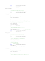
MotorUpdate:
MotorUpdate
Update the motor control settings based on a desired increase
or decrease in power as indicated in Arg1
Arg1 - the desired motor power percentage (0-100)
Arg2 - the desired direction (1=reverse, 0=forward)
nothing of any value
;
; Notes:
;
From the spec, CPRxH doesn't need to be set -- it's read-only in PWM mode
;
The low order 2 bits of duty cycle settings are in CCPxCON b5-4.
;
;
; default settings are for the motor to be turned off -- this will get changed
; as we parse the input (most likely)
;
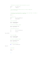
movlw MOTOR_SET_OFF
movwf MotorSettings, A
;
; get the passed in power percentage
;
movf
Arg1,W,A