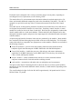
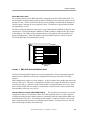
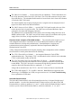
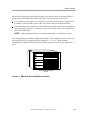
1
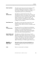
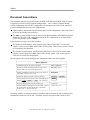
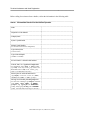
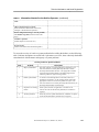
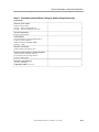
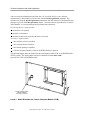
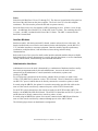
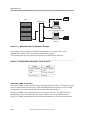
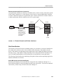
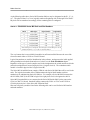
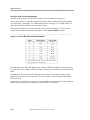
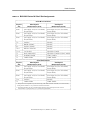
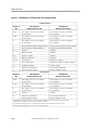
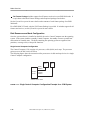
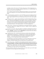
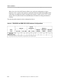
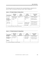
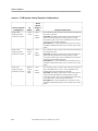
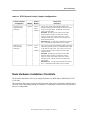
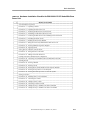
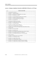
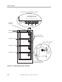
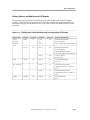
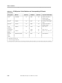
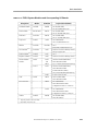
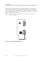
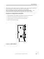
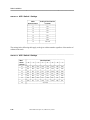
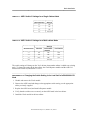
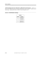
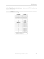
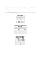
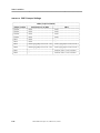
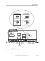
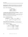
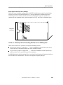
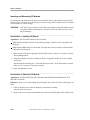
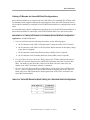
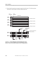
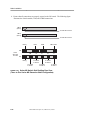
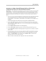
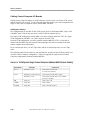
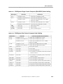
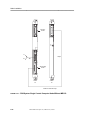
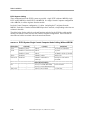
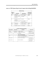
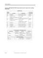
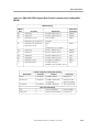
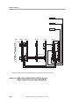
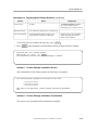
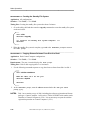
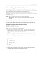
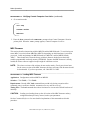
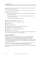
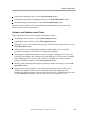
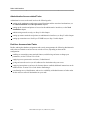
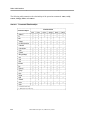
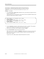
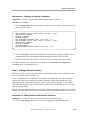
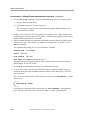
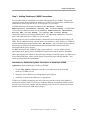
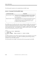
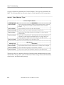
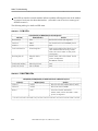
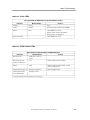
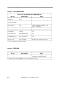
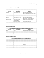
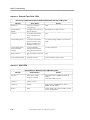
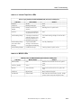
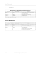
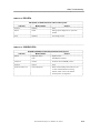
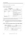
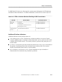
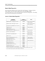
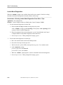
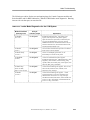
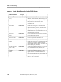
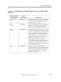
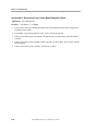
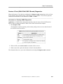
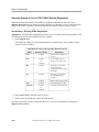
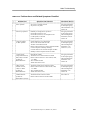
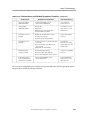
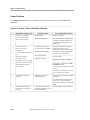
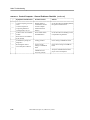
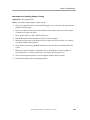
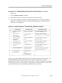
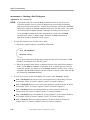
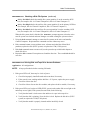
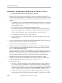
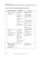
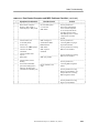
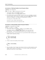
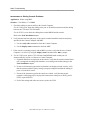
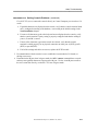
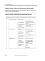
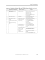
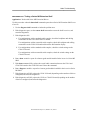
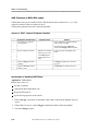
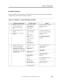
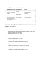
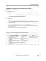
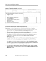
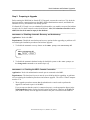
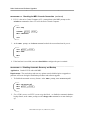
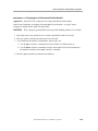
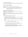
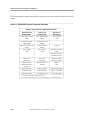
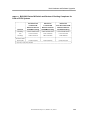
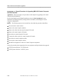
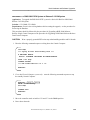
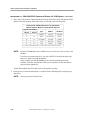
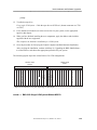
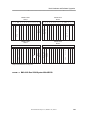
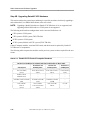
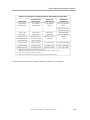
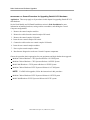
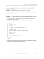
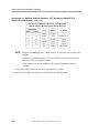
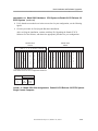
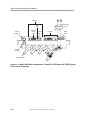
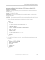
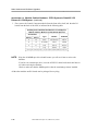
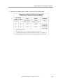
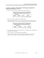
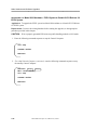
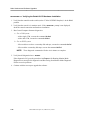
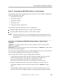
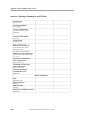
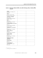
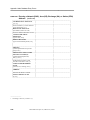
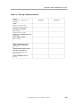
________________ Node Troubleshooting The following tables show LED states for power supplies. TABLE 6-20. Power Supply LEDs _______________________________________________________________________ Module or Hardware _______________________________________________________________________ Indicator Status Actions Green and Red Off No power or fault Check connections. Check for blown fuse in _______________________________________________________________________ power supply. If blown, replace power supply. _______________________________________________________________________ Power on Green Lit Red Lit Fault Replace power supply. The red LED may be lit if the shelf/cabinet is empty or the power supply is redundant. This does not always indicate a fault. For the SAM504, not applicable when the system is powering up. The red LED is on at power up _______________________________________________________________________ until the reset button is pressed. Green and Red Fault Replace power supply. (alternately blinking) _______________________________________________________________________ The following tables contain general information for LED indicators on most interface modules. For more specific information, see the individual module reference guide. NOTE: The CPM-HS, SFT, and TRK-HS modules are special cases. In addition to the LEDs on the front of the module, these modules have a special mute light on the I/O board. If this LED is red, it indicates a broken connection between the local and remote devices. TABLE 6-21. LEDS on Interface Modules Residing in the Node, SAMs, and MPCs __________________________________________________________________ __________________________________________________________________ Indicator Module Status Actions All 3 Off Not in service or fault Move mode switch to ENABL and restore the module. __________________________________________________________________ No power to module Verify that module has power. Green Lit On-line __________________________________________________________________ Yellow Lit Off-line Mode switch is in DISAB or DIAG position; move to __________________________________________________________________ ENABL. Red Lit Fault Disable, enable, and restore module. Run diagnostics on the module. __________________________________________________________________ 6-16 BNS-2000 Node Reference, Release 5.0, Issue 1