1
2102016_Land.qxp
1/11/2010
9:39 AM
Page 48
smaller mantissas. The result must be
0.5 < sum < 2.0. If the result is greater
than one, shift the mantissa sum right
one bit and increment the bigger input
exponent, to become the output exponent. The sign is the sign of either
input. If the signs of the inputs are different, subtract the bigger and (shifted)
smaller mantissas so that the result is
always positive. The result must be 0.0
< difference < 0.5. Shift the mantissa left
until the high bit is set, while decrementing the bigger exponent once per
shift, to become the output exponent.
The sign is the sign of the bigger input.
CONVERSION
February 2010 – Issue 235
It turns out that converting from
integer to float is fairly simple. I
assumed 10-bit, 2’s complement, integers since the mantissa is only 9 bits,
but the process generalizes to more
bits.
Save the sign bit of the input and
take the absolute value of the input.
Shift the input left until the high order
bit is set and count the number of
shifts required. This forms the floating
mantissa. Next, form the floating exponent by subtracting the number of
shifts from step 2 from the constant
48
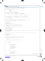
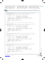
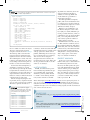
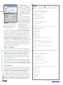
Listing 2—Verilog describing a fourth-order filter generated by a Matlab/Octave script.
//Filter: cutoff=0.100000
//Filter: cutoff=0.200000
IIR4sos filter4(
.audio_out (filter4_out),
.audio_in (audio_inR),
.b11 (18'h10300),
.b12 (18'h10500),
.b13 (18'h10300),
.a12 (18'h1037A),
.a13 (18'h30185),
.b21 (18'h10300),
.b22 (18'h30500),
.b23 (18'h10300),
.a22 (18'h103BC),
.a23 (18'h301B0),
.gain(18'hF749),
.state_clk(AUD_CTRL_CLK),
.lr_clk(AUD_DACLRCK),
.reset(reset)
) ; //end filter
137 or (0h89–(#of shifts)). Assemble the
float from the sign, mantissa, and
exponent.
Converting back to integer is similarly simple, but no overflow is detected,
so scale carefully. If the float exponent is
less than 0h81, then the output is zero
because the input is less than one. Otherwise, shift the floating mantissa to the
right by (0h89–(floating exponent)) to
form the absolute value of the output
integer. Form the 2’s complement
signed integer.
I coded the above outlines into Verilog for conversion to hardware on the
FPGA. I wanted to see how fast I could
make purely combinatorial floating
point execute, so there is no pipelining
or clocking of the arithmetic modules.
Remember that every statement in Verilog represents the signal on a wire or
bus, and therefore every statement can
change value simultaneously!
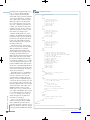
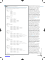
The code for the floating multiplier is
shown in Listing 1. The low-level,
unsigned, integer multiply of the mantissas is performed by a small module
which gives the Altera Quartus II software a hint that a hardware multiplier
should be used. The 9-bit × 9-bit multiply
yields 18 bits, of which nine are selected
for output in the asynchronous always
@(*) statement. All of the modules are
available on both the Circuit Cellar
FTP and the ECE5760 course website.
The Quartus II design software converted
this multiplier code to about 60 logic elements plus one hardware multiplier on
the Cyclone II FPGA (out of 33,000 logic
elements and 70 multipliers), while the
adder takes about 220 logic elements.
The timing analyzer suggests that the
purely combinatorial multiplier should be
able to run at 50 MHz and the adder at
30 MHz, and in fact run fine at 27 MHz.
DSP APP & TESTING
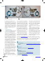
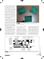
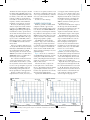
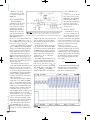
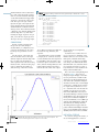
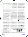
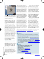
Figure 2—Computed and observed filter response. The line is the exact response. The
points are the observed floating-point filter response on the FPGA.
To test the floating-point modules, I
wrote a DSP application to filter an
CIRCUIT CELLAR®
•
www.circuitcellar.com