1
Chapter 6: Specifications - Analog I/O Modules
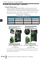
F2-08DA-2, Analog Output
Full Scale
Calibration Error
Offset Calibration
Error
Accuracy vs.
Temperature
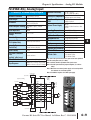
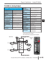
F2-08DA-2 8-Channel Analog Voltage Output
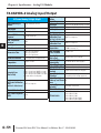
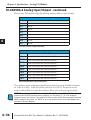
Number of Channels
Output Ranges
Resolution
Output Type
Base Power Required
5VDC
8, single-ended, 1 common
0 to 5V, 0 to 10V
12 bit (1 in 4096)
Voltage sourcing
Load Impedance
Load Capacitance
PLC Update Rate
Conversion Settling
Time
Linearity Error
(end to end)
±3 counts max., unipolar @ 25ºC (77ºF)
±57 ppm/ºC full scale calibration change
(including maximum offset change of 2 counts)
±0.3% @ 25ºC (77ºF)
Maximum Inaccuracy ±0.45% @ 0-60ºC (32-140ºF)
60 mA
Operating
Temperature
Storage Temperature
15 VDC
(clamped by transient voltage suppressor) Relative Humidity
Environmental air
1-10 k
Vibration
0.01 µF maximum
Shock
8 channels per scan maximum
Noise Immunity
400 µs maximum (full scale change)
4.5 ms to 9 ms for digital out to analog out Terminal Type
(included)
±1 count (±0.025% of full scale) maximum ZIPLink Module
VDC, 140 mA (outputs fully
External Power Supply 21.6-26.4
loaded)
Peak Output Voltage
±12 counts max. unipolar @ 25ºC (77ºF)
0º to 60ºC (32º to 140°F)
-20º to 70ºC (-4º to 158ºF)
5 to 95% (non-condensing)
No corrosive gases permitted
MIL STD 810C 514.2
MIL STD 810C 516.2
NEMA ICS3-304
Removable; D2-8IOCON
ZL-RTB20 (Feedthrough)
ZL-D2-CBL10 (0.5m)
ZL-D2-CBL10-1 (1.0m)
ZL-D2-CBL10-2 (2.0m)
ZIPLink Cable
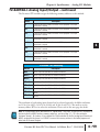
One count in the specification table is equal to one least significant
bit of the analog data value (1 in 4096).
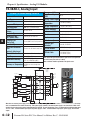
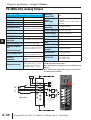
Note 1: Shields should be connected to the 0V of the module.
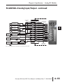
Typical user wiring
Internal
Module
Wiring
18--30VDC
@ 90mA
+
Internal module
wiring
--
0 VDC
S ee
NOTE 1
Ch 1 load
1K--10K ohms
minimum
+V1
DC to DC
Converter
+24 VDC
0V
Ch 1
Voltage s ource
+V3
+V4
D to A
Converter
0V
+24V
+V2
+V6
+V7
Ch 8 load
1K--10K ohms
minimum
F2-08DA-2
18-30VDC
80mA
ANALOG OUT
0-5VDC
0-10VDC
+V1
+V5
S ee
NOTE 1
ANALOG
A
8CH
+5V
+15V
--15V
+V2
OUT
+V8
+V3
Ch 8
Voltage s ource
D to A
Converter
+V4
+V5
+V6
+V7
+V8
F2-08DA-2
Do-more H2 Series PLC User Manual, 1st Edition, Rev. C - H2-DM-M
1
2
3
4
5
6
7
8
9
10
11
12
13
14
A
B
C
D
6–41