1
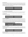
X1 mode, then you would receive 5000 pulses in X2 mode and 10,000 pulses in X4 mode. If the board will be used to
detect simple clock pulses then select Non-Quadrature mode.
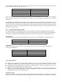
CMR Quadrature Scaling
Non-Quadrature
X1
X2
X4
4.2.2
Bit 3 & 4 value for quad scaling
x010 0xxx
x010 1xxx
x011 0xxx
x011 1xxx
Reset and Load Signal Decoders (RLD)
The RLD contains three user configurable fields. This register controls all of the reset options as well as the data transfer
options. The following sections describe each field in the RLD register and the various modes that can be set for operation.
The RLD register is used to reset the counter and the status flags and also to provide access to the error bit E, which is the
only means for resetting this flag once it is set.
RLD Reset Byte Pointer Field
This field is used to reset the byte pointer. The byte pointer is auto-incremented each time the Output Latch (OL) register is
read or the Preset Register (PR) is written to. The byte pointer must be reset prior to any access to the 24-bit counter
register.
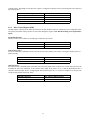
RLD Byte Pointer Reset
NOP
BP Reset
Bit 0 value for byte pointer reset
x00x xxx0
x00x xxx1
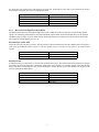
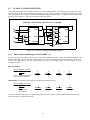
RLD Reset Fields
In addition to the byte pointer there are several other fields that can be reset. This field provides the mechanism for resetting
the counter and all of the status flags. The Borrow Toggle (BT), Carry Toggle (CT), Compare Toggle (CPT), and the Sign
Flag (S) can all be reset through bits 1 and 2 of the RLD register. Finally, the only way to clear the Error (E) flag once it has
been set is through the RLD register.
RLD Reset
NOP
CNTR
BT, CT, CPT, and S
E
Bit 1 & 2 value for reset fields
x00x x00x
x00x x01x
x00x x10x
x00x x11x
9