1
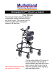
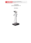
WALKABOUTTM WA1C & WA2C
User Manual
This manual contains essential guidance
for therapists, stores personnel, school
and home carers. This manual must be
read thoroughly before issuing this
product to an end-user.
It is the responsibility of the issuer to
know this product well enough to
ensure effective and safe set up and
also to ensure that the end-user is
This manual must be kept with aware of essential points regarding
the product at all times
safe and effective use.
Table of Contents
Preface
3
Design Goals
3
Safety Information
5-6
Precautions
7
Components
8
Assembly
9-12
Adjustment Overview
13
Fitting Instructions
13-19
Measure the Child
13
Sit Bar, Hip & Upper Trunk Supports
14
Upper Body Pitch
15
Column Height
16
Spring Tension
17
Swivel Caster Lock
18
Adjustable Length Base
18
Headrest
19
Anti Reverse Brake
19
Options / Accessories
20-26
Hand Holds & Arm Troughs
20
Clear Tray Assembly
21
Double Sit Bar
22
Abduction Skirt
22
Unicycle Saddle Seat
23
Shoulder Pads
24-25
Neck rest
26
Product Induction and Issue Directive
27-29
Using the Walkabout™
30-35
Maintenance / Monthly Checks
36-37
Inspection
38-41
Product Log
43-46
2
Preface
This manual provides the information required for the set up and use of
the WalkaboutTM 1 & 2C. This manual is for the EU users.
The benefits of using this system can be profound, not only in terms of
gait development, but also in terms of increasing the child’s
independence, self confidence and social interaction.
Design Goals
The WalkaboutTM is designed to give a child the potential for handsfree, self-initiated movement while providing lateral support and
assisted lift. This spring-assisted lift allows for graduated weight relief
as the child develops skill and standing tolerance. The adjustable
“pitch/ angle” of the column, along with the pelvic and trunk supports,
can be utilized to direct weight shift and assist with stepping.
Key For EU Users
T Technical User : Therapist
C School & Home Carer
S Store Personnel
3
Before Starting
T
C
S
Important
This walker should be used under the prescription and direction of
the child’s therapist.
Always read instructions before use. Failure to follow instructions
may impair use, impede function and more importantly may affect
the user’s safety.
This user guide is for WalkaboutTM, item Code: WA1C & WA2C.
Each product has a serial number which will be found on the base.
Please quote this number in all correspondence.
This product conforms to CE Marking Regulations, Medical Devices
Directive (MDD) 93/ 42 EEC,
Do not add any other accessories other than those supplied by
Mulholland to this product. Ring your local dealer for advice if unsure.
The warranty conditions are stated on page 42 and provide further
information.
WA1C: maximum user weight 25Kg.
WA2C: maximum user weight 36Kg.
Service or repair must only be carried out by a Mulholland authorised service person / local dealer. Any service or repair carried out
by any other person will invalidate the guarantee and Mulholland
cannot accept any liability for injury or damage thus caused.
The tools required to adjust WalkaboutTM are supplied with the
product. These adjustments are to be made by the therapist only.
Store these in a safe place. Keep away from children.
The WalkaboutTM should only be setup by the therapist.
Ensure that the product is fully assembled before use. Contact your
local dealer if you need advice at this stage.
Frequently check and tighten all loose fasteners. Loose fasteners
can cause the WalkaboutTM to be inoperable. See Page 40
It is essential that the WalkaboutTM is cleaned regularly so as not to
impede function and to remain hygienic. Use warm soapy water but
not abrasive detergents. See Page 37
Please ensure the WalkaboutTM is set up as per instructions. Ensure that induction / hand over procedures as described on page
27 are undertaken.
•
•
•
•
•
•
•
•
•
•
•
•
•
•
•
•
4
Before Starting
T
C
S
Safety
•
•
•
•
•
•
•
•
•
•
•
•
It is imperative that children are continuously monitored whilst using the WalkaboutTM. NEVER LEAVE A CHILD UNATTENDED IN
THIS PRODUCT.
If there is the slightest concern regarding the supports, use or function of the product then immediately contact your local dealer.
All adjustments should be carried out prior to transferring the user
into the WalkaboutTM. Only the fine height adjustment through the
crank lever at the top of the rear column should be carried out with
the user in the WalkaboutTM.
Ensure wheels are always locked when transferring the user into
the walker. The rear anti-tip wheel can be lower to provided additional stability. However, raise the wheel before using the
WalkaboutTM. The anti-tip wheel should clear the floor by 1”/ 25mm.
Once the user is transferred into the walker, secure the chest and
pelvic straps immediately.
When doing a hoist transfer, please ensure that the hoist sling is
not caught on any part of the WalkaboutTM.
Due to the nature of the product, please be aware of the length of
the base and the surroundings in which the WalkaboutTM is being
used.
Do not allow other individuals to use, play with, stand on, ride on or
run around the WalkaboutTM. Please be aware of the spring mechanism on the rear column, as fingers may accidentally get pinched.
Please ensure the WalkaboutTMis used on a level and even surface.
The WalkaboutTM should not be used near a slope, stairs or a
swimming pool.
Beware of obstacles ( curb, door stop, drains ) which can cause issue with WalkaboutTM stability.
Adjust the base frame length to suit conditions of use and the stature of the user.
Promote good hygiene. Do not allow the child to eat or suck the
webbing straps
5
Before Starting
T
C
S
Safety
Beware of the user’s excessive speed and the surroundings.
Do not exceed the maximum user weight or the maximum height
adjustment.
As the child develops walking and independence, be aware of hazards and skills that the child has not yet learnt, e,g hot surfaces,
electrical items etc.
The ball lock pin must be engaged at all times and the T-Nut must
be secure. Always use both the securing mechanisms at all times.
Failure to use the ball lock pin will allow the rear column to slide
downwards causing injury to the user. See page 35
When a sit bar / double sit bar or seat is used, ensure the ball lock
pin is engaged and the T nut is tight. Failure to secure the support
may allow the user to slide through the supports causing injury to
the user.
Ensure that the user does not get their feet caught under the base
or the wheels.
Please ensure appropriate footwear is used for walking in the
WalkaboutTM.
Ensure the user does not get their head behind the side of the
headrest, a wider headrest can be provided.
Strong involuntary movement or seizures may cause stability issues. DO NOT LEAVE CHILD UNATTENDED IN WALKABOUTTM
Beware some users may accidentally undo the chest and pelvic
buckles. If the user is able to undo the buckles and there is a risk of
the user falling out of the WalkaboutTM please immediately contact
your local dealer for advice and stop using the WalkaboutTM.
Small parts if loose will be a potential hazard for small children.
Keep products away from sources of heat such as naked flames,
cigarettes, open fires, heaters, radiators etc.
•
•
•
•
•
•
•
•
•
•
•
•
The safety advice and directions in this manual cannot cover all
eventualities and unforeseen situations that may occur. It must be
understood that common sense, general caution and care are factors that cannot be built into this product. These are factors which
the person actually using this product must assume responsibility
for.
•
6
Precautions
T
C
S
Before transferring the user into the WalkaboutTM, ensure initial
checks are carried out as directed on Page 35.
Ensure the user is well supported when transferring into the
WalkaboutTM.
Always use all the straps provided, Ensure the chest and pelvic
straps over lap each other by minimum of 2”.
Always secure the secondary plastic buckle on the chest and pelvic straps.
Please ensure that items of clothing and hair are fastened away,
so as not to impede or get caught in the WalkaboutTM spring
mechanism.
This device is NOT to be used as a transportation device
especially in motor vehicles.
Never make any tilt adjustments with the child in the
WalkaboutTM.
The rear anti-tipper wheels need to be at least 1 inch (2.5cm) off
the floor. If they are contacting the floor the user cannot turn in
the device.
Adjust the height of the seat prior to putting the user in the
WalkaboutTM.
Adjust the spring tension after the user has been transferred into
the WalkaboutTM.
If the rear column tilts forward spontaneously correct the angle
and TIGHTEN the clamp screws. See Page 10.
7
WalkaboutTM Components
1. Pelvic support
2. Trunk support
3. Front column
4. Head rest
5. Spring stop assembly
6. Crank
7. Rear column
6
T
8. Tube adjustment clamps
9. Column brace
10.Base frame
11.Anti-tipper wheels
12.Toggle brake
13.Sit bar
Figure 1
5
4
7
2
1
9
3
8
13
10
12
8
C
11
S
2
Unpacking & Assembly
T
S
Unpack the box carefully, WalkaboutTM is shipped in 3 Parts (base, front
and rear column assembly, and column adjustment tube with the rear
tipper wheels) plus accessories. Carefully remove all the parts from the
box and check you have all the parts you have ordered.
Keep bubble wrap and polythene bags away from children
Tools Required:
•
•
•
•
3/16” Allen wrench (included in pouch)
5/32” Allen wrench (included in pouch)
1/4” Allen wrench (included in pouch)
Tape measure
Common Adjustment Fasteners
Adjustment Levers:
Refer to Figure 2.
The adjustment levers can be ratcheted
so that the handle can rotate without
affecting the tightness of the screw.
1. Pull out on black knob. Rotate the
handle so it is not obstructed.
2. Release the black knob, and let the
handle slide back and lock with the
screw.
3. Continue tightening/loosening the
screw by rotating the handle.
Figure 2
Ball Lock Pins:
Refer to Figure 3.
1. Hold the pull ring of the pin with your
index finger.
2. Pull on the ring to extract, or push
the pin to insert.
Figure 3
9
Assembling The WalkaboutTM
T
Column Adjustment Tube:
Refer to Figure 4.
1. Place the base assembly on the floor
and apply the brakes.
2. Loosen the rear two Allen screws on
each of the 2 tube adjustment
clamps (1). Figure 4B.
3. Remove the front Allen screws from
each of the 2 tube adjustment
clamps (2).
4. Slide the column adjustment tube
(3) through the tube clamps.
5. Replace the front two Allen screws
on the tube adjustment clamps. (Do
not tighten yet)
6. Position the column adjustment tube
(3) so that the anti-tipper wheel (4) is
at least 1” from the ground. Figure
4C.
7. The “stop” on the column adjustment
tube should rest on top of the bottom
tube adjustment clamp. Figure 5.
8. Tighten the front two Allen screws
first, and then tighten the back four
screws until they are “snug.”
S
3
1
2
Figure 4
Figure 4B
3
Do not over tighten the
screws, this will cause the column adjustment tube to
buckle and inhibit adjustment!
Having the anti-tipper wheels
on the ground will make it extremely difficult for the user to
turn in the unit.
4
1”
Figure 4C
10
Assembling The WalkaboutTM
T
S
Note : the column adjustment tube
(3) is mounted inside the base - with
the wheel on the outside.
Figure 5
Column
Refer to Figure 6.
2
1. Loosen the T-nut (1) and pull the column adjustment plunger /ring (2) on
the rear column adjustment tube.
2. Slide the rear column (3) into the
column adjustment tube.
3. Release the plunger and tighten the
T nut to secure the rear column to
the base.
Ensure the column adjustment
plunger has fully engaged with
the selected hole on rear column and the T nut is tight.
1
3
Figure 6
11
Assembling The WalkaboutTM
T
S
Completed Assembly:
Refer to Figure 7.
Figure 7
12
Adjusting The WalkaboutTM
AJUSTMENT OVERVIEW
T
Proper adjustment of the WalkaboutTM will significantly improve the
child’s success. The therapist is encouraged to try various adjustment
combinations. As the child’s skill improves, adjustments should be
made to decrease the amount of assistance.
Key Adjustments:
• Column Tilt (Pitch / Angle): Affects the child’s orientation in space
and can affect posture and tone.
• Column Height: Affects the degree of assistance that the stander
provides (in addition to spring tension)
• Pelvic and Trunk Supports: Provide precise proximal stability. These
components also provide some of the fine tuning for trunk alignment
and control.
• Spring Tension: Spring support can be increased or decreased by
turning crank (refer to the Components section for location Page 8)
FITTING INSTRUCTIONS
Taking the following measurements will ensure the WalkaboutTM is set
up correctly for the user.
Measure the Child:
1. Trunk width: _________
2. Hip width: _________
3. Inside Leg to 1” below his/her axilla: _________
4. Inside Leg to floor : _________
13
T
Adjusting The WalkaboutTM
Sit Bar, Pelvic & Trunk
Supports:
1
Refer to Figure 8.
5
1. Open the front of the pelvic & trunk
support straps by releasing the
4
buckles, and unfastening the velcro.
2. Loosen the four Allen screws (1) on
the back of the sling bar clamps.
3. Adjust the width of the trunk bars to
accommodate the trunk width
measurement). The bars should be
symmetrical on both sides. Tighten
3
the four Allen screws.(1)
4. To adjust the width of pelvic support
2
to required measurement, repeat
steps 2 & 3.
5. Sit bar height: Remove the ball lock
pin (2) and loosen the T-nut (3). Slide
Figure 8
the sit bar along the front column.
Initially, place the sit bar as high as
possible on the column. Replace the
ball lock pin, tighten the T-nut.
6. Pelvic support height: Loosen the two adjustment levers (4) on the
back of the clamp plates. Place the pelvic support assembly as close
to the sit bar as possible without preventing hip flexion. If this support
is too high or too low, it will not provide the stability required for the
child to step forward. Tighten both levers.
7. Trunk support height: Loosen the two adjustment levers (5) on the
back of the clamp plates. Position the trunk support so the distance
from the top of the trunk support to the top of the sit bar is equal to
required measurement. Tighten both adjustment levers.
After adjusting the sit bar, ensure the ball lock pin is completely
engaged in the selected hole and T nut is tight. Failure to secure
the bar properly may allow the user to slide through the pelvic
and trunk supports causing injury to the user.
14
T
Adjusting The WalkaboutTM
Pitch:
Refer to Figures 9 & 10.
The child’s shoulders should be
positioned slightly in front of the lower
body and feet (in most situations) with
the pitch of the column at
approximately 85 degrees to the floor.
Occasionally the column will be
positioned in a more upright, or more
prone position, to improve the child’s
gait pattern or to diminish primitive
reflex patterning.
1. To achieve forward tilt of the upper
body, unfasten the trunk support
straps, shorten the back strap, and
lengthen the front strap. Lengthening
the back strap and shortening the
front strap tilts the upper body
backward.Figure 9
2. If more pitch is needed, the rear
column can be tilted forward. Loosen
the 3 Allen screws on the upper tube
clamp assembly (Fig 10). Raise the
upper clamp assembly and frame
brace while tilting the column forward
(Fig 10A).When the desired angle is
achieved tighten the Allen screws to
secure the column. Note: lowering
the upper tube clamp assembly will
tilt the column back upright.
Do not over tighten the screws,
this will cause the column adjustment tube to buckle & inhibit adjustment
Figure 9
1
Figure 10
Figure 10A
15
Adjusting The WalkaboutTM
T
Column Height:
3
DO NOT ADJUST WITH CHILD IN
WALKER!
Refer to Figure 11.
2
1
After setting the pitch and the sit bar-totrunk support distance, set the column
height.
1. Determine the child’s sit bar height
using inside leg measurement.
a) If the child requires upper support
to stand, add 50 mm to inside leg
measure..
Figure 11
a) If the child requires only hip
support to stand, then use the inside leg measure.
1
2. Adjust the Column Height:
a) Loosen the T-nut (1) and pull the
column adjustment ring on the
rear column adjustment tube.
b) Slide the rear column (2) up/down
so that the sit bar height is the
same as the inside leg height
determined above.
c) Release the rear column adjustment ring ensuring it is fully
seated back in the column and
tighten the T-nut to secure the rear
column in place.
d) For more precise adjustments,
rotate the crank (3) clockwise to
raise the column assembly or
counterclockwise to lower the
column assembly.
16
Figure 11A
3
Figure 11B
T
Adjusting The WalkaboutTM
Spring Tension:
Refer to Figure 12.
The sit bar, pelvic support, and trunk
support assist in supporting the child
into standing. The amount of lift is
controlled by the degree of spring
tension.
2
1
3
1. Spring rate adjustment: The spring
rate is the amount of force required
to compress the spring by a given
amount. By sliding the black tubular
spring stop (1) down, the spring
becomes stiffer. To adjust, depress
the silver slide lock button (2) and
hold it in to release the spring stop.
Figure 12
2
2. Slide the spring stop up/down to
adjust the spring assistance.
Release the slide lock button to lock
the spring stop in the desired
position.
3. For additional spring adjustment,
rotate the crank (3) clockwise to
increase the spring tension or
counterclockwise to decrease the
spring tension. Note: this adjustment
can also be used to affect the height
of the front column.
1
Figure 12A
3
After adjusting the spring stop
ensure the silver slide lock button returns to the lock position.
Figure 12A.
Figure 12B
17
T
Adjusting The WalkaboutTM
Adjustable Length Base:
1
Refer to Figures 13 & 14.
To extend the base of the WalkaboutTM
simply pull up on the ring (1) and slide
out the extension tube to the desired
length. Both sides should be set to the
same length. Ensure pin is locked into
tubing for security
Adjust the length to suit the
conditions of use. Extend the
legs for play or for outdoor use.
The Walkabout™ may become
unstable if the legs are too short
Figure 13
Swivel Lock:
Refer to Figure 15.
The swivel lock pin can be turned to
drop down and lock the wheel into
position, or alternatively, pulled back up
and turned to allow the wheel to swivel.
Unlocked
Pull & Twist
18
Figure 14
Locked
Twist & Release
Figure 15
T
Adjusting The WalkaboutTM
Anti Reverse Brake:
1
Refer to Figure 16.
1. To engage the anti reverse brakes,
turn the knob (1) clockwise, until the
wheel cannot spin backwards, but
can still spin forwards.
2. For free wheel movement, & to release the anti-reverse turn the knob
(1) counterclockwise.
Figure 16
Adjusting the Brakes:
Refer to Figure 17.
Lightly tighten the two screws (1). Do
not over tighten as the brake lever
won’t lock. Tighten the screws until the
brake clicks on and clicks off. If the
wheel still turns then the complete
brake assembly needs to move forwards by undoing the screws (2).
1
2
Figure 17
Headrest:
Refer to Figure 18.
2
1
To adjust the height of the headrest (1),
loosen the Allen screw (2) in the clamp
on top of the column. Slide the
headrest up/down until it is in the
desired position. Retighten the Allen
screw.
Ensure the user does not get
their head behind the side of the
headrest, a wider headrest can
be provided.
Figure 18
19
Adjusting The WalkaboutTM - Accessory
T
Handholds with arm troughs:
Refer to Figures 19,19A,19B & 19C.
1. Mounting: Hand holds with arm
troughs are mounted on the back of
the sit bar (3). Secure the arm
troughs to the sit bar with the four Allen screws and lock nuts. Figure
19A. It is easiest to mount with the sit
bar removed from the column.
2. Width: The width is adjusted by
removing the ball lock pins (1) on the
cross bar and sliding the tubes
inwards or outwards. Figure 19A
3. Height: The height can be adjusted
by loosening the clamps (2) and
moving the hand hold posts up or
down. Tighten the clamp again when
adjusted to fit. Figure 19B
4. Forearm support can be adjusted by
loosening the four Allen screws (4).
Arm hold can be adjusted by loosening the Allen screws (5). Figure 19C.
5. Reattach the sit bar to the front column.
1
2
3
Figure 19
1
Figure 19A
1
2
Figure 19B
20
4
Figure 19C
5
Adjusting The WalkaboutTM- Accessory
T
Clear Tray Assembly:
Refer to Figure 20.
Mounting: The tray mounting arms
attach to the back of the sitbar, just like
the hand holds. Please refer to page 20 Always store the tray on the
for instructions.
arms to avoid damage and obAdjustments:
struction.
1. Height: Refer to the Handholds
instructions on page 20.
2. Depth: Pull the ring on the spring
clamps (1), located underneath the
tray. Slide the tray along the tray bar
to the desired depth. Release the
ring and ensure the tray locks into
place.
3. Removing the tray: The tray must be
removed to place in, or take the child
from the Walkabout™. This is done
by pulling the rings on the spring
clamps (1) and lifting the tray off the
support bars.
1
Figure 20
21
Adjusting The WalkaboutTM - Accessories
T
Double Sit Bar:
Refer to Figure 21.
1
1. Remove the current seat or single sit
bar.
2. Slide the sit bar onto the front
column. Secure at the desired
height with the ball lock pin (1) and
tighten the T nut.
Figure 21
Abduction Skirt:
Refer to Figure 22.
1. Remove the current seat option.
2. Slide the abduction skirt onto the
front column. Secure at the desired
height with the ball lock pin and
tighten the T nut.
1
Figure 22
After adjusting the double sit bar or the abduction skirt, ensure
the ball lock pin is fully engaged and T nut is tight. Failure to secure the support properly may allow the user to slide through the
pelvic and trunk supports causing injury to the user.
22
Adjusting The WalkaboutTM - Accessories
T
Unicycle Saddle Seat:
Refer to Figures 23A & 23B.
Mounting:
1. Remove the single or double sit bar.
2. Slide the sit bar onto the front
column. Secure at the desired
height with the ball lock pin (1) and
tighten the T nut.
Adjustments:
1. Height: Remove the ball lock pin (1)
and slide the saddle seat along the
front column to the desired height.
Replace the ball lock pin.
2. Depth: Loosen the knob (2). Slide
the saddle seat along the seat bar to
the desired depth. Tighten knob.
3. Seat Angle: Loosen the four 1/4 nuts
(3), underneath the saddle seat. Tilt
the seat to the desired angle and
tighten the nuts to secure.
1
2
Figure 23A
3
Figure 23B
After adjusting the seat, ensure the ball lock pin is engaged and
T nut is tight. Failure to secure the support properly may allow
the user to slide through the pelvic and trunk supports causing
injury to the user.
23
Adjusting The WalkaboutTM - Accessories
T
Shoulder Pads:
Refer to Figure 24.
Mounting:
1. To mount the shoulder pads, first
remove the headrest pad. Do this by
loosening the two Allen screws
securing it to the vertical hex bar
coming out of the top of the column.
(1)
2. Then, slip the shoulder pads onto the
top of the bar as shown in Figure 24
A.
1
2
Figure 24
Adjustments:
1. Height: Loosen the Allen screw on
the bracket (3). Slide the shoulder
pads to the desired position, and
retighten the screw.
2. Width: (Refer to Figure 24C) Loosen
the set screw (4) on the bottom of
the pivot pin receiver (5). Slide the
receiver along the hex cross bar (6)
to the desired width. Tighten the set
screw. Repeat on opposite side.
3. Depth: (Refer to Figure 24C) Loosen
the bar clamp (7) by loosening the
Allen screw (8) on the side. Loosen
the lock pin block (9) by loosening
the allen screw (10) on the side.
Slide the shoulder pad back/forth to
the depth which provides the
appropriate amount of anterior
support. Align the lock pin block (9),
with the plunger pin (which is inside
24
3
Figure 24A
3
Figure 24B
Adjusting The WalkaboutTM - Accessories
T
Shoulder Pads: Cont’d.
the lock pin block) on top so the
shoulder pad will lock in position
when in use and when pivoted out
of the way. Tighten the Allen screw
(10) to secure the lock pin block
(9). Slide the bar clamp (7) against
the pivot pin receiver (5) to
provide enough tension to lock the 8
pivot. Tighten the Allen screw (8)
to tighten the bar clamp (7).
Repeat for both sides.
6
4. Pivoting the shoulder pads: The
shoulder pads can be pivoted out
of the way while placing the child in
or removing the child from the
stander. Pull the ring (11) on the
back of the plunger pin to release the
pivot. To open, rotate the shoulder
pad away from the
column until the pivot
locks. To replace, pull
the ring and rotate the
shoulder pad in the
opposite direction
until it locks.
7
5
9
4
11
10
Figure 24C
7
5
9
11
3
6
4 10
Figure 24 D
We recommend that the shoulder pad should be used with either the neck rest or
the head pad. If shoulder pads are to be used without head pad or neck rest,
please be aware that the metal work at the rear of the shoulder pad may come in
contact with the user’s head and cause injury.
25
Adjusting The WalkaboutTM - Accessories
T
Neck rest:
Refer to Figure 25.
Mounting:
1. To mount the Neck rest, first remove
the headrest pad. Do this by
loosening the two Allen screws
securing it to the vertical hex bar
coming out of the top of the column.
(1)
2. Then, slip the Neck rest onto the top
of the bar as shown in Figure 26.
Adjustment:
Height : To adjust the height of the neck
rest, loosen the Allen screw (2) in the
clamp on top of the column. Slide the
Neck rest up/down until it is in the
desired position. Retighten the Allen
screw.
Depth: To adjust the depth of the neck
rest, loosen the two Allen screws (3).
Slide the Neck rest backwards / forwards until it is in the desired position.
Retighten the Allen screws.
1
2
Figure 25
3
Figure 26
26
Product Induction and Issue Directive
T
This product has been prescribed by the therapist or practitioner who
should read the instruction manual and be fully aware of all available
adjustments.
The prescriber has the responsibility to ensure the product is correctly
set up to meet the client’s needs, including the induction to the carer(s)
or home user.
A formal procedure for issuing Mulholland products to the users must
be implemented by using the forms /check list provided in this user
manual. These forms /check lists are to assist the prescriber in ensuring that the product issued is safely used and maintained. Each time
the product is re-issued, a new manual must be provided.
• It is imperative that the product log form is completed at the rear of
•
•
•
•
•
•
this manual on a regular basis. This form must be used to record setups, changes to the product and scheduled maintenance checks undertaken.
It is imperative that all users understand the CORRECT USE of the
product and also what is INAPPROPRIATE USE.
All users must understand and appreciate all SAFETY aspects of the
WalkaboutTM.
CARE, MAINTENANCE AND CLEANING procedures must be implemented to ensure client well being.
TOOLS issued for adjustment are for the technical users ONLY. Adjustments should NOT be undertaken by the carers or home users.
CARERS AND HOME USERS MUST BE AWARE. This product has
been prescribed by the therapist or practitioner for a specific child
and should ONLY be used as directed by the prescriber.
To validate the warranty it is important that each section of the end
user log is actioned, recorded and initialled each time the
WalkaboutTM is reviewed.
27
Product Induction and Issue Directive
T
Re-issue
Before re-issue all checks and maintenance procedures MUST be undertaken as outlined in this manual. (See re-issuing on page 38)
To validate the warranty it is important that each section of the Product
Log is actioned, recorded and initialled.
28
Product Induction and Issue Directive
Important Issuing Information
T
This form must be completed on
issue or re-issue of the product
Child’s Name
Therapist’s Name
Therapist’s Address
Therapist’s Telephone
Primary Carer’s Name
Product Issue Date
Product Serial No.
Product Purchase Date
Induction Check List
Please ensure that the following sections are covered with the primary
carer before the product is issued. Please initial each box when instructing carer / end user through the induction process
Safety Information
Using the Walkabout
Care & Maintenance
Cleaning
Product Log Updated
Induction Given By:
Induction Received By
Date
29
Using the WalkaboutTM
T
C
S
Brakes
Refer to Figure 27
Pull the brake lever back to apply the
brakes. To release the brakes push the
brakes in the opposite direction.
Fitting the rear column to
base
Refer to Figure 27A
1. Loosen the T-nut (1) and pull the column adjustment plunger /ring (2) on
the rear column adjustment tube.
2. Slide the rear column (3) into the
column adjustment tube.
3. Release the plunger and tighten the
T nut to secure the rear column to
the base. Position height of the
rear column as advised by the prescribing therapist.
Height adjustment and
spring tension of front
column
Figure 27
3
1
2
Refer to Figure 27B
1. For additional spring adjustment:
rotate the crank (1) clockwise to
increase the spring tension or
counterclockwise to decrease the
spring tension. Note: that this
adjustment can also be used to adjust the height of the front column.
Only use if advised by the prescribing therapist.
30
Figure 27A
1
Figure 27B
Using the WalkaboutTM
T
Adjustable Length Base:
1
Refer to Figures 28 & 28A
C
S
To extend the base of the WalkaboutTM
simply pull up on the ring (1) and slide
out the extension tube to the desired
length. Both sides should be set to the
same length.
Adjust the length to suit the conditions
of use. Extend the legs for play or for
outdoor use.The Walkabout™ may
become unstable if the legs are too
short for the conditions of use. Ensure
the pin is secured into tubing and extension tube is locked into position.
Figure 28
Swivel Lock:
Refer to Figure 29.
The swivel lock pin(1) can be turned to
drop down and lock the wheel into
position, or alternatively, pulled back up
and turned to allow the wheel to swivel.
Unlocked
Pull & Twist
Figure 28A
Locked
Twist & Release
Figure 29
31
Using the WalkaboutTM
T
C
S
Chest & pelvic Straps
Refer to Figure 30.
Secure the strap by overlapping the
padded strap. Ensure at least 2” /
50mm overlap exist between each of
the two straps. Once the padded straps
are secured , fasten the secondary
strap securely with plastic buckles.
To release the straps undo the plastic
buckles and peel the padded strap
apart.
Figure 30
Handholds with arm troughs
Refer to Figures 31 & 32.
To reattach the handholds to the
WalkaboutTM. Side the Handhold into
the outer tube located at the back of the
sit bar(1) and secure with the ball lock
pin. (2)
1
Figure 31
2
Figure 32
32
Using the WalkaboutTM
T
C
S
Clear Tray Assembly:
Refer to Figure 33.
To secure the tray pull the ring on the
spring clamps (1), and place tray on top
of the tray bars. Slide the tray back and
forth until the spring clamp locates into Always store the tray on the
the tray bars.
arms to avoid damage and obstruction.
To remove the tray, pull ring on the
spring clamp and lift off the tray.
1
Figure 33
Shoulder Bars:
Refer to Figure 34.
Pivoting the shoulder pads: The
shoulder pads can be pivoted out of the
way while placing the child in or
removing the child from the stander.
Pull the ring (1) on the back of the
plunger pin to release the pivot. To
open, rotate the shoulder pad away
from the column until the pivot locks.
1
Figure 34
33
Using the WalkaboutTM
Anti Tipper Wheel
Refer to Figure 35.
T
C
S
1
To assist transfer lower the anti tip
wheel down by removing the ball lock
pin. Lower the anti-tip wheel and secure with the ball lock pin
After transfer, return the anti-tip wheel
to the original setting and secure.
Always maintain minimum 1” space
between the anti-tip wheel and the
ground
34
4
1”
Figure 35
Using the WalkaboutTM
T
C
S
Initial Checks
Before placing the user into the
WalkaboutTM, we recommend the following checks should be carried each
time.
1. The brakes are in working order.
2. The rear column is secured to the
base with the ball lock pin and the T
nut.
3. The sit bar or abduction skirt is secured to the front column with the
ball lock pin and the T nut.
4. The front skis are locked. We recommend the skis should be used on
max. setting for greatest stability.
5. Chest and Pelvic Velcro is clean and
the safety buckles are in good working condition.
See Using WalkaboutTM section for
more information.
1
3
2
4
35
Maintenance
T
C
S
This product has been prescribed by the therapist or practitioner who
must ensure that all users understand and implement correct use,
safety checks, care, maintenance and cleaning. It is the user (carer for
the child) who is responsible for ensuring the product is correctly used
on a daily basis. The therapist should direct the following checks to be
undertaken:, the frequency of the check stated is a minimum and
should be undertaken depending on the environment and level to which
walkabout is used.
Monthly Checks
The monthly check: again the frequency is only a minimum and frequency should be adjusted depending on the environment in which the
equipment functions. As this check is a more in-depth check a suitably
competent individual should be nominated by/on behalf of the prescriber.
Check the Following:
1. The brakes are in working order.
2. The rear column is secured to the base with the ball lock pin and the
T nut. Check the rear column is tightly secured to the base page 10.
The column brace should not be moving See page 8.
3. The sit bar or abduction skirt is secured to the front column with the
ball lock pin and the T nut.
4. The front skis are locked. We recommend the skis should be used
on max. setting for greatest stability.
5. Chest and pelvic velcro is clean and the safety buckles are in good
working order.
6. Chest and pelvic supports are secure and tight, especially the width
and height adjustment fasteners.
7. The spring stop assembly is secure and in good working order.
8. The crank handle allows fine height and spring tension adjustment.
9. The four key pivot points are in good working order and all eight fasteners are tight.
10.Check any additional accessories are working in good order.
11.Replace any missing or worn bolts / fixings as required.
12.Check WalkaboutTM frame for wear and tear, splinter, breaks
13.Check the overall structure of the WalkaboutTM for any signs of fatigue or damage.
14.Ensure product log sheet is completed and signed.
36
Maintenance
Cleaning :
• Metalwork and coated parts can be wiped with soapy water or anti-
•
bacterial spray. Please dry the product thoroughly. Please do NOT
use solvents, abrasive cleaners, caustic soda, sodium hypochlorite
or organic solvents.
Pelvic support, chest supports, and sit bar should be wiped regularly
with soapy water or antibacterial spray. Please dry material thoroughly after wiping. Please do not soak the fabric.
37
Reissuing / Annual Inspection
T
C
S
Please ensure that WalkaboutTM is maintained and that appropriate
logs are kept as per MHRA guidelines. Please refer to the following bulletins for further information
Managing Medical Devices - DB2006(05) November 2006
Medical Devices and Equipment Management :
Repair and Maintenance Provision -MDA DB2000(02) June 2006
• Mulholland products are assessed for an individual client. Therefore
the following points must be observed before re-issuing any Mulholland product.
• Check with the issuing therapist that product is standard and that no
special attachments or modifications have been made. If modifications have been made then contact Mulholland or your local dealer
for advice.
• Each product has a serial number located on the WalkaboutTM base.
Do not remove this label.
• Follow the inspection guide on the next page. Regularly fill in the
product log sheet to record all services and repairs to the product
regularly.
• To validate the warranty it is important that each section of this manual is actioned, recorded and initialled.
• Check that the product has been fully cleaned.
• Check the product and any key accessories carefully for any signs of
•
•
•
•
wear and tear or distortion. Replacements can be supplied.
Check that all functions of the product are working correctly and fitted e.g.Chest support, pelvic support, sit bar and headrest etc .
Check all fixings, levers and knobs are in good condition, functional
and secure.
Always ensure that a new manual is supplied each time product is
re-issued. For new sets of instructions please contact Mulholland or
your local dealer or e-mail us at info@mulhollandinc.com.
The old user manual returned with the WalkaboutTM MUST be
passed onto the therapist.
38
Inspection List
T
S
1. Ensure the brakes are in working order. See page 19 for how to
adjust the brakes.
2. The rear column is secured to the base with the ball lock pin and the
T nut. Check the rear column is tightly secured to the base page 10.
The column brace should not be moving See page 8.
3. The sit bar or abduction skirt is secured to the front column with the
ball lock pin and the T nut.
4. Check the front skis locks in all the positions. See Page 31
5. Check the swivel direction lock is in working order. See Page 31
6. Check that chest and pelvic Velcro is clean and the safety buckles
are in good working order.
7. Check all upholstery for wear and tear, including headrest ankle
straps etc.
8. Check that chest and pelvic supports are secure and tight, especially
the width and height adjustment fasteners.
9. Check the spring stop assembly is secure and in good working order.
10.Check the crank handle allows fine height and spring tension adjustment.
11.Check the four key pivot points are in good working order and that
all eight fasteners are tight.
12.Check any additional accessories are working and in good order.
13.Replace any missing or worn bolts / fixings as required.
14.Check WalkaboutTM frame for wear and tear, splinter, breaks
15.Check the overall structure of the WalkaboutTM for any signs of fatigue or damage. The base must be level and all four wheel must
make contact with the floor.
16.Release the anti reverse brakes and swivel lock then check that the
WalkaboutTM is freely moving and not veering to one side. See Page
18 & 19.
17.Check the anti tip wheel is in working order. See Page 34.
18.Check the push and pull handle is secure on the metal work.
19.Ensure product log sheet is signed.
20.Check the fasteners as detailed on the next two pages. Pages 4041.
If there is any doubt regarding the WalkaboutTM, please do not issue
and contact Mulholland or local dealer immediately for support. We are
happy to help.
39
Fastener check
T
S
Please check the following fasteners.
Rear Column : Figure A
There are 5 fasteners on each side of
the WalkaboutTM. Ensure all ten fasteners are tight.
Base : Figure B
Ensure the 6 screws are tight
Do not over tighten the
screws, this will cause the
column adjustment tube to
buckle and inhibit adjustment!
Chest & Pelvic Supports :
Figure C.
Ensure 6 screws are all tight, (four on
one side two on the other side).
Figure C
40
Figure A
Figure B
Fastener Check
T
S
Spring Tension : Figure D
Depress the silver slide lock button (2)
and slid the spring stop up and down.
Check that the silver slide lock engages
at each of the notches on the side of
the spring stop.
2
1
Front Wheels: Figure E
Check the wheels are moving freely
and that the cross pin is tight.
Rear Wheels: Figure F
Figure D
Check the wheels are moving freely
and the cross pin is tight.
Figure F
Figure E
41
Servicing
T
S
The Mulholland Walkabout™ is guaranteed for 2 Years from the date of
purchase. It is recommend that the Walkabout™ receives an annual
service when out of guarantee. Service is only to be carried out by Mulholland authorised personnel. Please contact you local dealer for more
information.
Limited Warranty
Mulholland Positioning Systems Inc warrants Mulholland Positioning
System’s equipment to be free of all defects in material and workmanship for 2 years in the UK from date of shipment.
Mulholland Positioning System Inc will repair or replace such part or assembly which upon examination is found by the manufacturer to be defective under normal use and service.
Since positioning results obtained with the use of our equipment depend on circumstances beyond our control, we cannot assume and we
disclaim responsibility for expense, damage or injury of any kind associated with the use of the equipment sold by recognised dealer and/or
manufactured by Mulholland Positioning Systems Inc.
Misuse, negligence, accident and/or physical modification of Mulholland
Positioning Systems Inc are not covered in this warranty.
Mulholland Positioning Systems Inc or local dealers are not obligated to
bear the cost of transportation charges in connection with the replacement or repair of defective parts. In all cases, transportation charges to
the factory must be prepaid.
Mulholland Positioning Systems Inc give no other warranty, expressed
or implied, in relation to the product it manufacturers .
42
Product Log
Date
Setup/ Checks
T
Signature
C
S
Print Name
43
T
Product Log
Date
44
Setup/ Checks
Signature
C
S
Print Name
Product Log
Date
Setup/ Checks
T
Signature
C
S
Print Name
45
Product Log
Date
46
Setup/ Checks
T
Signature
C
S
Print Name
WalkaboutTMSpecification
T
C
S
Specifications:
Physical Unit
Weight:
Weight Limit:
Seat Height:
Tilt Range:
Width:
Length:
Turn Radius:
Frame Color:
Upholstery
Color:
WA 1C
WA 2C
26.5 lbs(12 kg)
55 lbs(25 kg)
7.5-24.5” (18.7-61.2cm)
75°-90°
22.5”(49.5cm)
25-30”(55-66cm)
14-19”(38-48cm)
Corvel Red
31 lbs(14 kg)
80 lbs(36 kg)
10.5-31”(26.5-77cm)
75°-90°
24”(53cm)
31-38”(68-84cm)
18-23”(40-50cm)
Royal Blue
Black
Black
Materials:
Frame:
Parts:
Padding:
Fabric:
Bumpers:
Wheels:
Powder-coated aluminum tube
Stainless steel tube
Powder-coated aluminum
Black anodized aluminum
Neoprene foam
Nylon packcloth
Solid gray cushion rubber with delrin bearing
Solid gray cushion rubber with double seal
ball bearings
47
839 Albion Ave P.O. Box 70 Burley, ID 83318
Phone:(208) 878-3840 (800) 543-476
Fax: (208) 878-3841
info@mulhollandinc.com
UK Dealer
EC REP
EU Authorised Representative
Wellkang Ltd
T/A Wellkang Tech Consulting 29 Harley Street, London W1 9QR
Tel: 02 3287 6300
48
P.O.Box 2125 Wolverhampton
WV6 7FB
Tel: 0845 459 2517
Fax: 0845 459 2518
W: www.a1active.co.uk
E: Enquire@a1active.co.uk