1
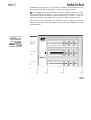
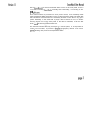
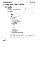
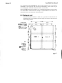
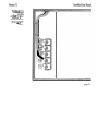
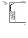
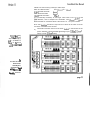
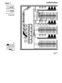
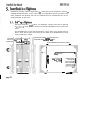
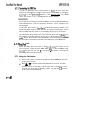
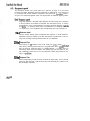
The door mounts on the left side of the rack, and supports all the rack electronics.
ounting the Smart ack door i s the last part of the installation procedure.
a)
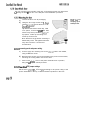
remove the door from its packaging.
b)
Using the two hinge screws and 3.5mm
spacers provided, mount the door in the
SmartRack chassis.
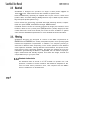
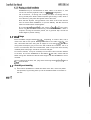
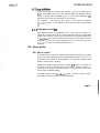
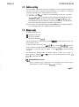
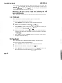
Fining the hinae screws
Tip: Extend the bottom screw fully, slide
on a spacer, a n d fit into
first. Then,
with the top screw protruding 3-4mm, fit
top spacer, locate top mounting and
screw top screw home.
Note that the fit of the bottom mounting is
deliberately loose. This tightens automatically when the door i s closed and
screwed shut.
'yg
lnge screw -""-
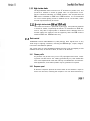
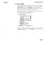
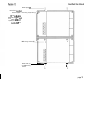
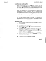
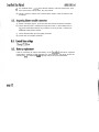
onnecting earth and power wiring
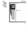
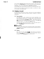
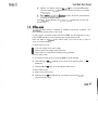
a)
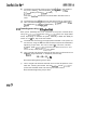
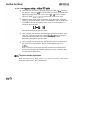
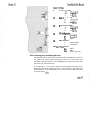
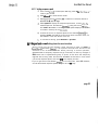
Connect front door earthing wire to the adiacent stud in the chassis,
using an M4 nut runner.
b)
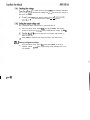
Route the CPU power loom and terminate to the power terminal block,
following the coding labels on the loom wires.
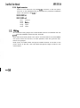
c)
Fix the clear plastic cover of the power terminal block in position,
using the M5 taptite screws provided.
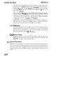
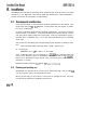
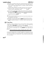
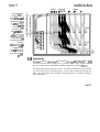
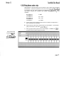
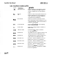
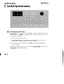
martRack CPU jumper settings
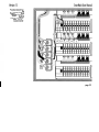
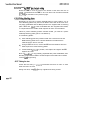
Set the three iumpers J1, J2 and 53, according to the power rating of the
power assemblies in the top, middle and bottom positions in the rack: